Motor with rotor balancer

A rotor balance and motor technology, applied in the field of motors, can solve the problems of easy structure loosening, noise generation, magnetic flux leakage, etc., and achieve the effect of improving rotation balance, improving floating height and vertical vibration.

Inactive Publication Date: 2008-02-27
DELTA ELECTRONICS INC
View PDF3 Cites 0 Cited by
  • Summary
  • Abstract
  • Description
  • Claims
  • Application Information

AI Technical Summary

Problems solved by technology

The disadvantage of such a rotor balancing device is that the balancing piece that provides the rotor balancing effect is an independent component and is fixed on the circuit board. This additional component not only increases the overall volume of the fan and the number of components, but also has a long-term effect on the motor. The entire structure is easy to loosen and generate noise under operation; more obviously, in order to fix the balance plate on the circuit board, the balance plate needs to be made into a shape with large corners and a part of the area is hollowed out, and the magnetic material The formed balance piece protrudes outside the closed magnetic circuit formed by the original stator and rotor, which will lead to obvious magnetic flux leakage problems

Method used


Image

  • Motor with rotor balancer
  • Motor with rotor balancer
  • Motor with rotor balancer

Examples


Embodiment Construction

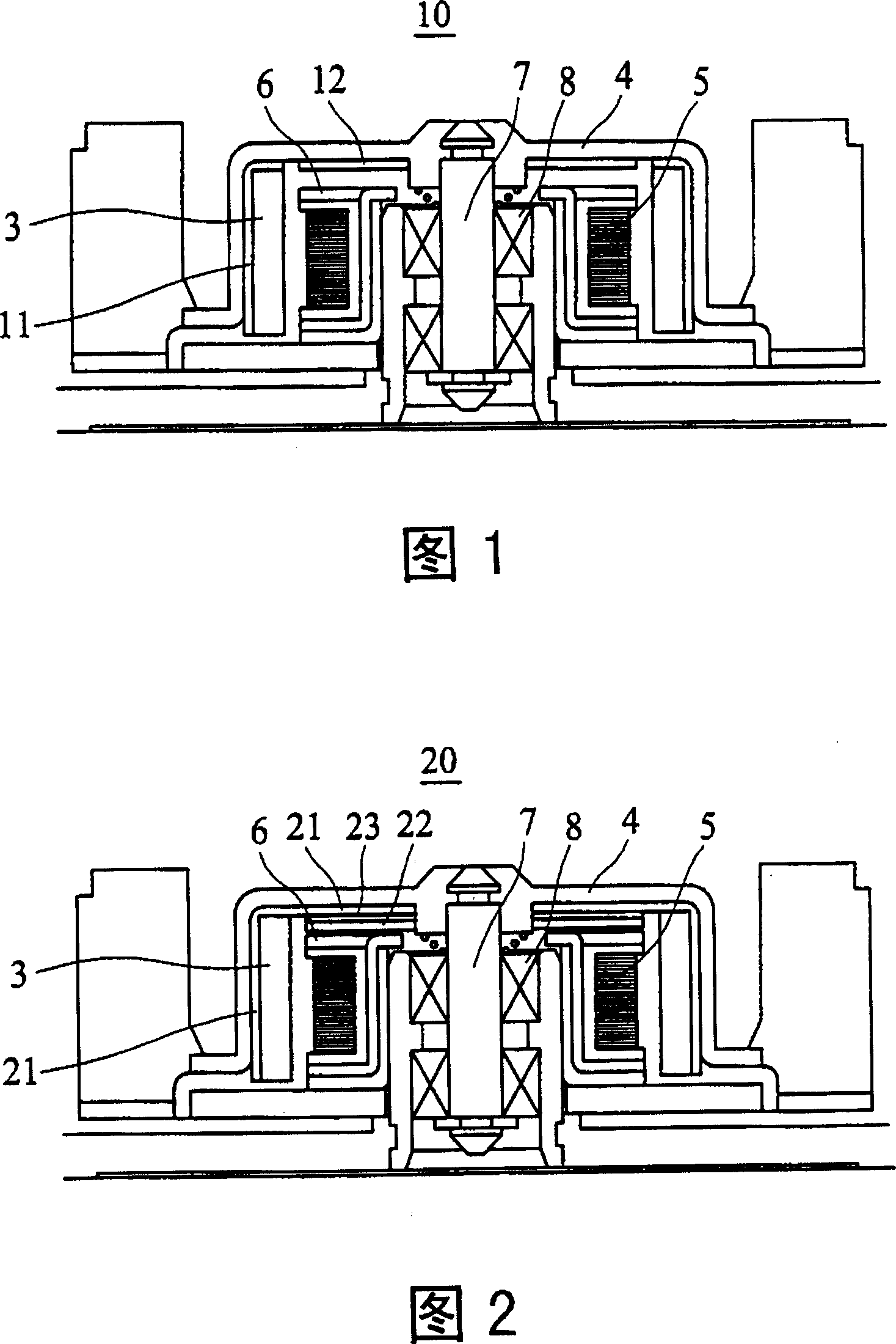
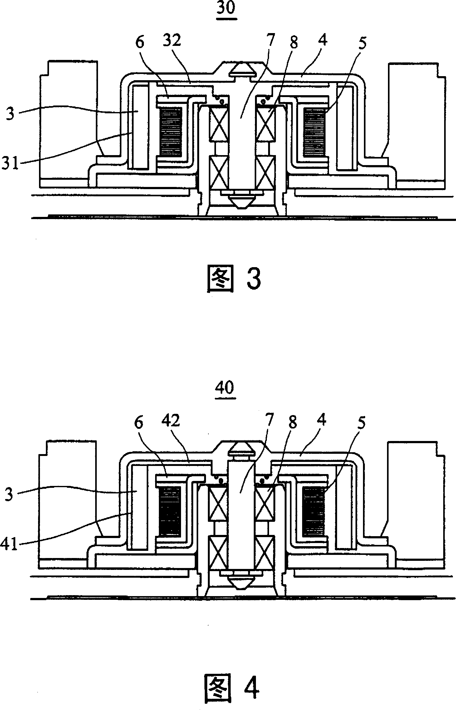
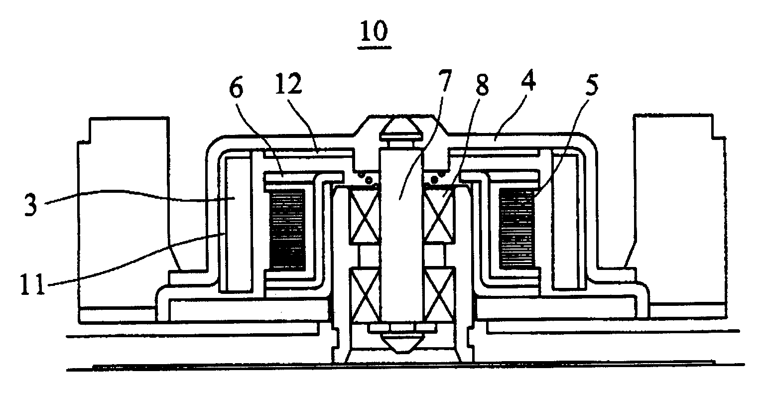
[0034] A rotor balancing device according to a preferred embodiment of the present invention will be described below with reference to related drawings. The same components will be represented by the same symbols.

[0035] Referring to Fig. 1, the motor 10 with rotor balancing device of the present invention comprises an iron shell 11, a magnetically conductive sheet 12, a magnetic tape 3 and a fan blade housing 4, wherein the fan blade housing 4 is slightly cup-shaped, and the outer ring is provided with A plurality of fan blades; the iron shell 11 is a ring, installed on the inside of the fan blade shell 4, and extends slightly towards the center near the top of the fan blade shell 4; the magnetic tape 3 ring is located inside the iron shell 11; The magnetic sheet 22 is directly disposed on the inner top of the fan blade casing 4 and is not in contact with the iron casing 11 . The stator includes a coil 5 and a silicon steel sheet 6 . The rotor balancing device 10 cooperat...


PUM


Abstract

A rotator balance device includes a segment shell, an iron whell inside the segment shell with the magnetic band matching with a stator including a coil and a silicon steel sheet. The rotation of the rotator balanced device can be performmed by electrically-exciting magnetism of coil on the stator via magnetic conducting silicon steel sheet to suck the magnetic band. The magnetic conducting sheet which has no magnetic conducting relation with the iron shell and has magnetic force with the coil arranged at the top of segment inside downwards to improve the flyhigh and vibration when the rotator is rotating up and down as well as to increase the rotating balance performance of the rotator balance device.

Description

【Technical field】 [0001] The invention relates to an electric motor with a rotor balancing device. 【Background technique】 [0002] When the rotor of the motor rotates, for example, the force of the air relative to the blades on the rotor or the change of the direction of the electromagnetic force will cause the rotor to float up or vibrate up and down, causing problems such as noise or component wear. [0003] FIG. 4 is a schematic diagram showing the combination of a conventional rotor structure and a stator, wherein the rotor structure includes an iron shell 41 , a magnetic tape 3 and a blade shell 4 . The blade casing 4 is slightly cup-shaped, and a plurality of fan blades are arranged on its outer ring; the iron casing 41 is also cup-shaped, and is arranged inside the fan blade casing 4; The stator includes a coil 5 and a silicon steel sheet 6 . The rotor is matched with the shaft 7 and the bearing 8 in the stator. When the coil 5 on the stator is excited by electricit...

Claims


Application Information

Patent Timeline
Patent Type & Authority Patents(China)
IPC IPC(8): H02K15/16
Inventor 林国正黄文喜周初宪蔡明熹
Owner DELTA ELECTRONICS INC
Why Eureka
Try Eureka