Card connector

一种卡连接器、误连接的技术,应用在连接、导电连接、两部件连接装置等方向,能够解决不能发现等问题,达到确保接触力的效果

Inactive Publication Date: 2008-03-05
DDK LTD
View PDF5 Cites 1 Cited by
  • Summary
  • Abstract
  • Description
  • Claims
  • Application Information

AI Technical Summary

Problems solved by technology

However, in the known literature, we have not been able to find any means to obtain this appropriate contact force

Method used


Image

  • Card connector
  • Card connector
  • Card connector

Examples


Embodiment Construction

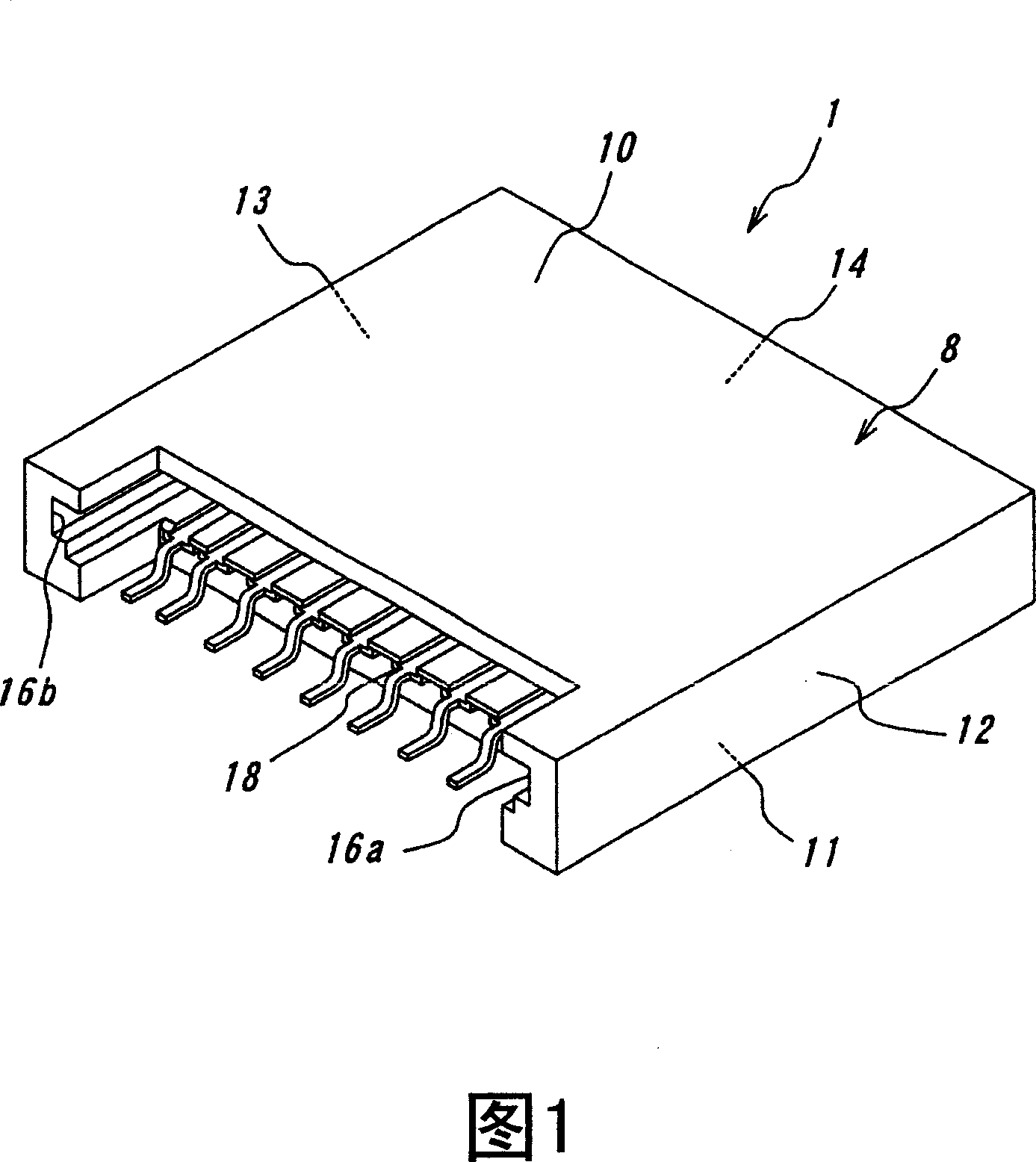
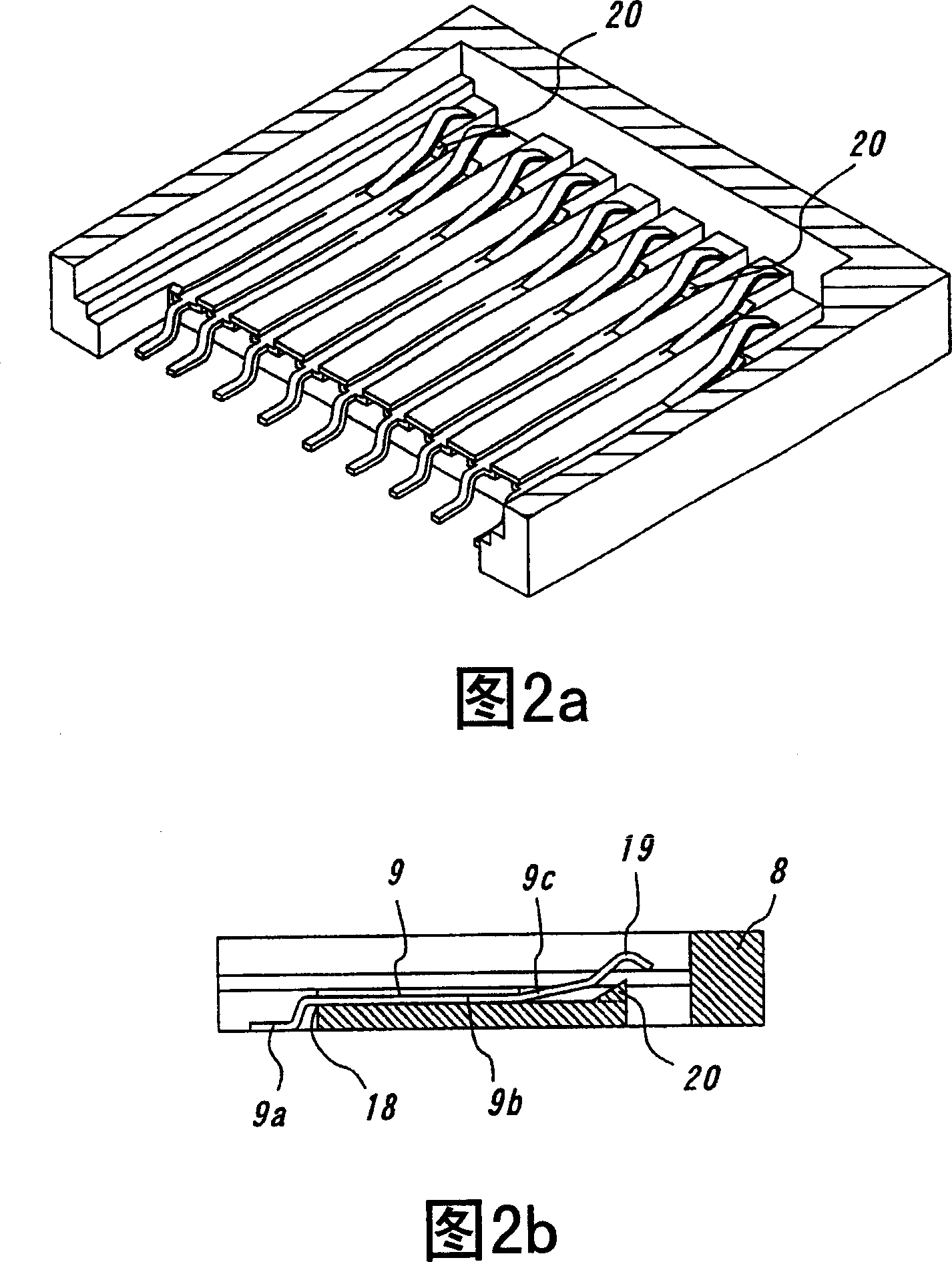
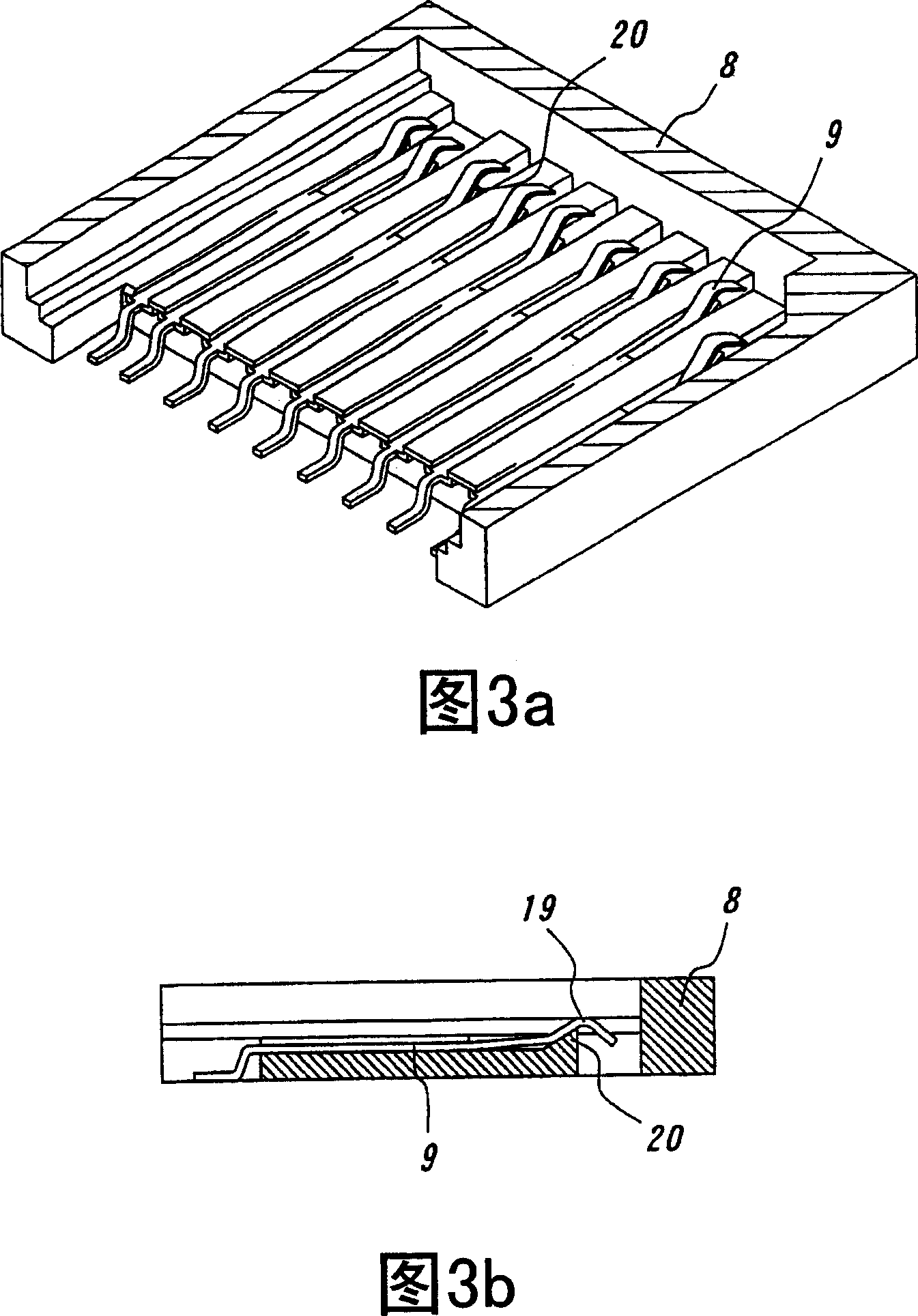
[0025] The best mode for carrying out the invention will be described below with reference to the accompanying drawings. Figure 1 shows a typical card connector according to the invention in perspective view. Figures 2a and 2b and Figures 3a and 3b show a card connector having a card connector housing with the upper portion of the housing removed for ease of illustration. Figures 2a and 3a show, in perspective views, the card connector contact terminals before and after a card (not shown) is normally loaded, respectively. Figures 2b and 3b also show cross-sectional views of the card connector taken along the longitudinal centerline of the contact terminals in the states of Figures 2a and 3a, respectively. Figures 4a and 4b are plan and sectional views of the card, and Figures 4c and 4d are partial plan and sectional views, respectively, of the card connector prior to card insertion. 5a and 5b are plan and sectional views, respectively, of the card and the card connector when...


PUM


Abstract

A card connector for use with an electronic appliance through an IC card having a plurality of recesses extending from its front end toward its rear end in parallel with one another and contact pads each being received in the recess. The card connector includes a connector housing and contact terminals. The connector housing has a pair of guide grooves for supporting and guiding both side edges of a card being inserted into the card connector and an insertion space in the housing for the inserted card. The contact terminals made of a springy and electrically conductive material are arranged in the connector housing and each have a contact portion adapted to contact with a contact pad of the card normally inserted in the card connector. According to the invention, the card connector comprises support protrusions each provided at a location below at least the contact portion of the contact terminal to limit the downward displacement of the contact portion of the contact terminal when the card has been normally inserted in the card connector, thereby ensuring a contact force more than a predetermined value between the contact portions of the contact terminals and the contact pads of the card.

Description

technical field [0001] The present invention relates to a card connector for various electric appliances such as mobile or cellular phones, digital cameras and the like. Background technique [0002] Electrical appliances such as mobile phones and digital cameras are usually designed to be able to be loaded into IC cards (integrated circuit cards), and CPUs or ICs of memory are embedded in IC cards. This IC card is, for example, a multimedia card for various function expansions. ). [0003] A device widely used to detachably mount such an IC card into an electric appliance is a card connector in which a plurality of contact terminals 102 are provided in a connector housing 101 as shown in FIGS. 7a and 7b. These contact terminals 102 are adapted to be connected to various circuits (not shown) on the side of the appliance. As shown in FIG. 8, when the card 103 is inserted into the card connector, the contact portions 108 of the contact terminals 102 are each in conductive c...

Claims


Application Information

Patent Timeline
Patent Type & Authority Patents(China)
IPC IPC(8): H01R13/193H01R13/629H01R13/64H01R12/22B42D15/10G06K17/00H01R9/16H01R24/00
CPCH01R9/16
Inventor 武井一统高桥宏和
Owner DDK LTD
Why Eureka
Try Eureka