Exchange type power supply and oscillator frequency adjuster thereof

A power supply, oscillator frequency technology, applied in the direction of collectors, irreversible AC power input to DC power output, electric vehicles, etc., can solve problems such as incompetence

Inactive Publication Date: 2008-03-12
DELTA ELECTRONICS INC +1
View PDF2 Cites 0 Cited by
  • Summary
  • Abstract
  • Description
  • Claims
  • Application Information

AI Technical Summary

Problems solved by technology

In this case, the known switching power supply will not be able to drive the load because the load power has exceeded its maximum load driving capability.

Method used


Image

  • Exchange type power supply and oscillator frequency adjuster thereof
  • Exchange type power supply and oscillator frequency adjuster thereof
  • Exchange type power supply and oscillator frequency adjuster thereof

Examples


Embodiment Construction

[0030] An exemplary embodiment with features and advantages of the present invention will be described in detail in the following description. It should be understood that the invention is susceptible to various changes in various respects, all without departing from the scope of the invention, and that the description and drawings therein are to be regarded as illustrative in nature and not for limitation. this invention.

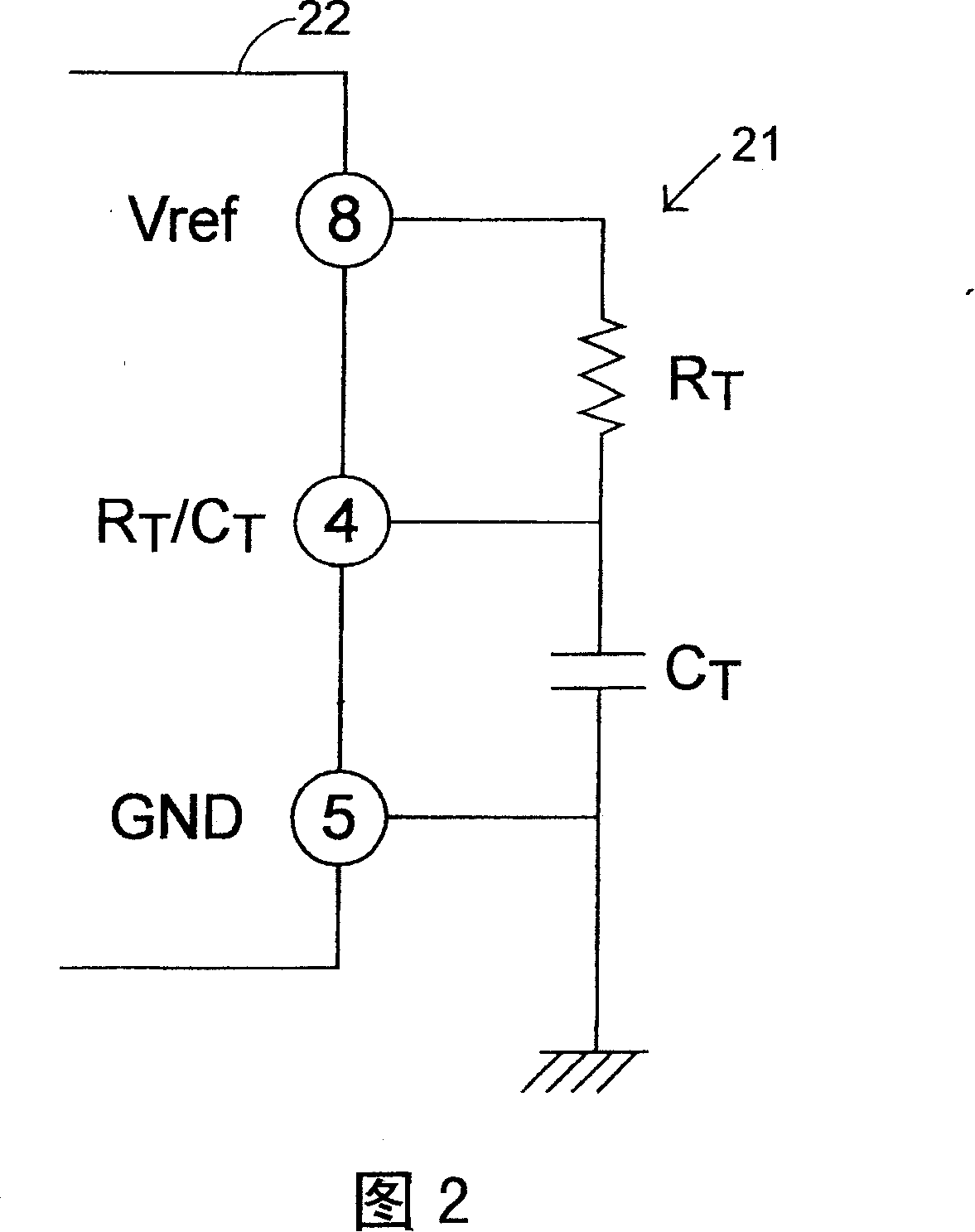
[0031] Referring to FIG. 2 , a conventional UC3843 current mode PWM controller 22 is partially shown and combined with a control circuit 21 . In this exemplary embodiment, the UC3843 PWM controller 22 is used as a standard example of the switching control circuit 16 in a switching power supply. In Figure 2, a resistor R T with an oscillation clock capacitor C T The control circuit forming the pulse width modulation controller 22 is respectively connected between the eighth leg position and the fourth leg position of the pulse width modulation controller...


PUM


Abstract

The invention relates to an exchange type power supply and oscillator frequency adjuster thereof, wherein the oscillator frequency adjuster comprises a reference voltage outlet connected to a switching control circuit, a plurality of capacitors connected to an ground-engaging end, at least a by-pass switch in cross-over connection with at least a capacitor for controlling the charging and discharging operation for the capacitor connected therewith, and a by-pass switch controller for controlling the switching status of the by-pass switch.

Description

technical field [0001] The present invention relates to a switching power supply (switching power supply) and its oscillator frequency regulator, in particular to a switching power supply, which uses an oscillator frequency regulator to dynamically adjust the switching power supply A switch of the oscillator controls the oscillator frequency and the maximum duty cycle of the circuit, and further enhances the load driving capability of the switching power supply under peak load conditions. Background technique [0002] A standard display of a switching power supply is depicted in Figure 1. In the switching power supply shown in FIG. 1 , the rectifier 11 is used to receive an input AC voltage Vin and convert the input AC voltage Vin into a rectified DC voltage. A switch device 12 is coupled between an output terminal of the rectifier 11 and a primary winding of a transformer T1. Transformer T1 is provided to receive the rectified DC voltage from its primary winding, and acts...

Claims


Application Information

Patent Timeline
Patent Type & Authority Patents(China)
IPC IPC(8): H02M7/04H02J7/00
Inventor 雅各琼哈艾威罗比逊库马堂东舒帕朋易塔沙客蔡桂湘
Owner DELTA ELECTRONICS INC
Why Eureka
Try Eureka