Silicon steel sheet, iron core linear motor, linear motor platform and led testing and sorting equipment
A linear motor, silicon steel sheet technology, applied in sorting, electromechanical devices, electrical components, etc., can solve the problems of motor excitation lag, unfavorable acceleration performance and precise control, large motor inductance, etc., and achieve the effect of large load driving capacity
- Summary
- Abstract
- Description
- Claims
- Application Information
AI Technical Summary
Problems solved by technology
Method used
Image
Examples
no. 1 example
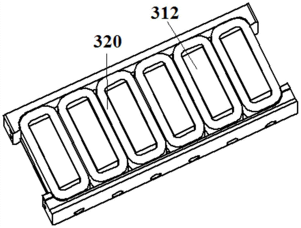
[0043] image 3 A schematic diagram of a core and coil 320 according to a first embodiment of the present invention is shown.
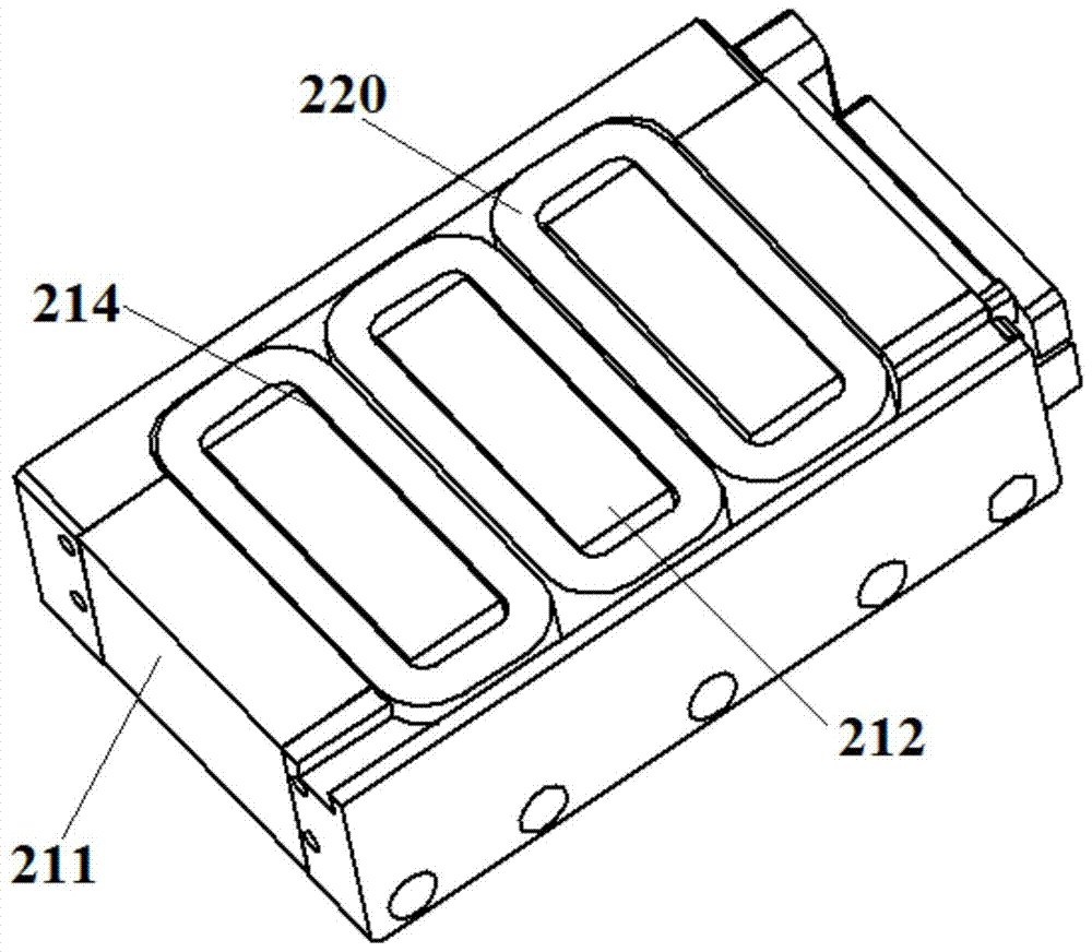
[0044] and figure 2 shown in the core compared to the image 3 Among the teeth of the iron core shown, the side teeth located at the edge ( figure 2 211) in is completely removed, leaving only the centrally located teeth 312 for winding the coil 320 thereon.
[0045] Through experiments and electromagnetic simulation calculations, it is found that the attraction and cogging force between the coil assembly and the magnet assembly can be effectively reduced by removing the side teeth, and the general reduction range is between 10% and 25%. If it is combined with other reduction The method of cogging force, such as magnet tilting, etc., can reduce the cogging force by more than 80%. At the same time, with the removal of the side teeth, the mass of the iron core is also reduced.
[0046]Preferably, the number of middle teeth 312 is an integer multi...
no. 2 example
[0061] Figure 5 A schematic diagram of a core and coil 520 according to a second embodiment of the present invention is shown.
[0062] and figure 2 shown in the core compared to the Figure 5 Of the teeth of the iron core shown, the side teeth 511 located at the edge portion are partially removed. Therefore, the height is lower compared to the centrally located teeth 512 for winding the coil 520 thereon. The height of the side teeth 511 may be about 3 / 4 to about 2 / 3 of the height of the middle teeth 512 .
[0063] Through experiments and simulation calculations, it is found that as long as part of the tooth 511 is cut off, the effect of reducing the attractive force and the cogging force between the coil assembly and the magnet assembly can be achieved. It is known through experiments and simulations that when about 1 / 4 to about 1 / 3 of the side teeth are cut off, sufficient attraction force and cogging force can be reduced. There is a limit to the further reduction in ...
no. 3 example
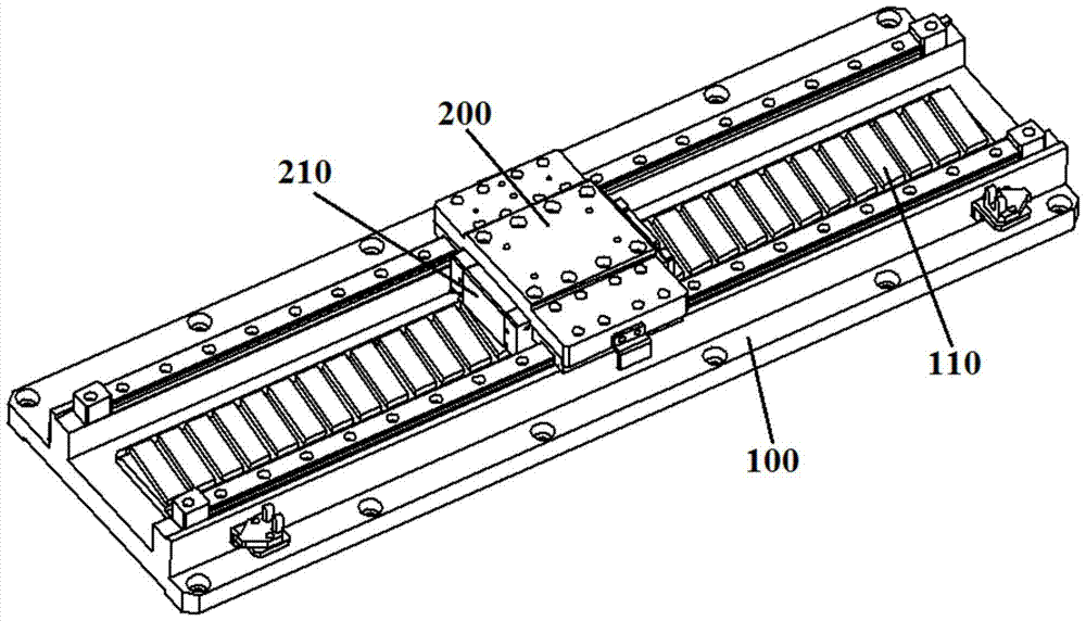
[0075] Figure 7 A schematic diagram of a linear motor platform according to a third embodiment of the present invention is shown.
[0076] Figure 7 The linear motor platform shown includes an X-direction (first) iron-core linear motor located at the lower part and a Y-direction (second) iron-core linear motor located at the upper part.
[0077] The base plate 710 and other components fixed on the base plate 710, such as the X guide rail, the X magnet assembly 720, the X limit switch, the X linear displacement sensor, etc., together constitute the X stator part of the X-direction iron core linear motor. Although the figure schematically shows guide rails, limit switches, linear displacement sensors, etc., in order to avoid obscuring the essence of the present invention, no detailed description is given here.
[0078] An X iron core 740 is installed on the X mover part 730 of the X direction iron core linear motor.
[0079] The Y stator part of the iron core linear motor in...
PUM
 Abstract
Description
Claims
Application Information
 - R&D
- Intellectual Property
- Life Sciences
- Materials
- Tech Scout
- Unparalleled Data Quality
- Higher Quality Content
- 60% Fewer Hallucinations
Browse by: Latest US Patents, China's latest patents, Technical Efficacy Thesaurus, Application Domain, Technology Topic, Popular Technical Reports.
© 2025 PatSnap. All rights reserved.Legal|Privacy policy|Modern Slavery Act Transparency Statement|Sitemap|About US| Contact US: help@patsnap.com


