Program compiling device using computor
A computer and program technology, which is applied in the field of program writing devices, can solve problems such as impaired readability and obstruction of table-style program description, and achieve the effects of improving work efficiency, reducing inappropriateness, and simplifying calculation and processing
- Summary
- Abstract
- Description
- Claims
- Application Information
AI Technical Summary
Problems solved by technology
Method used
Image

Examples
Embodiment approach 1
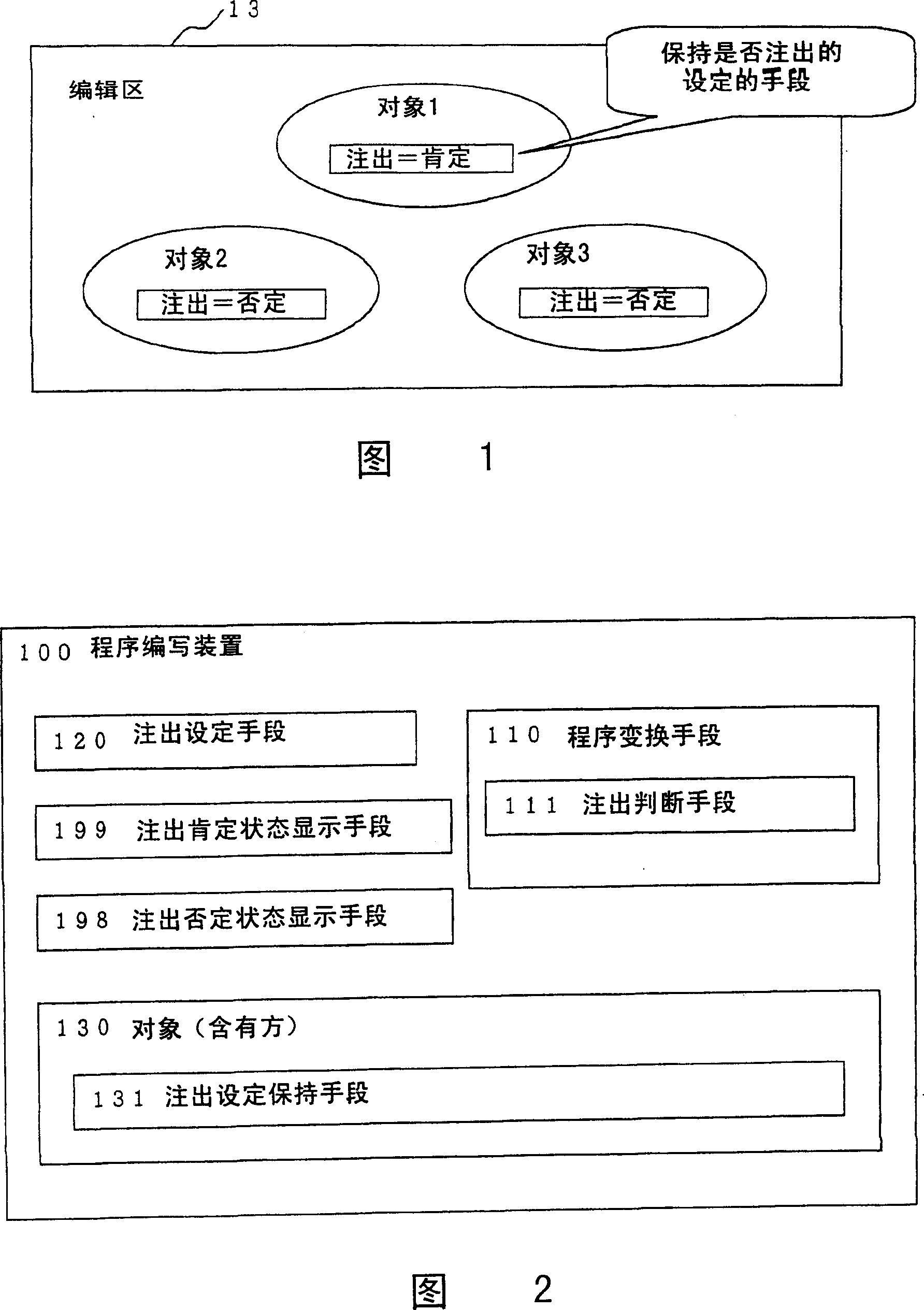
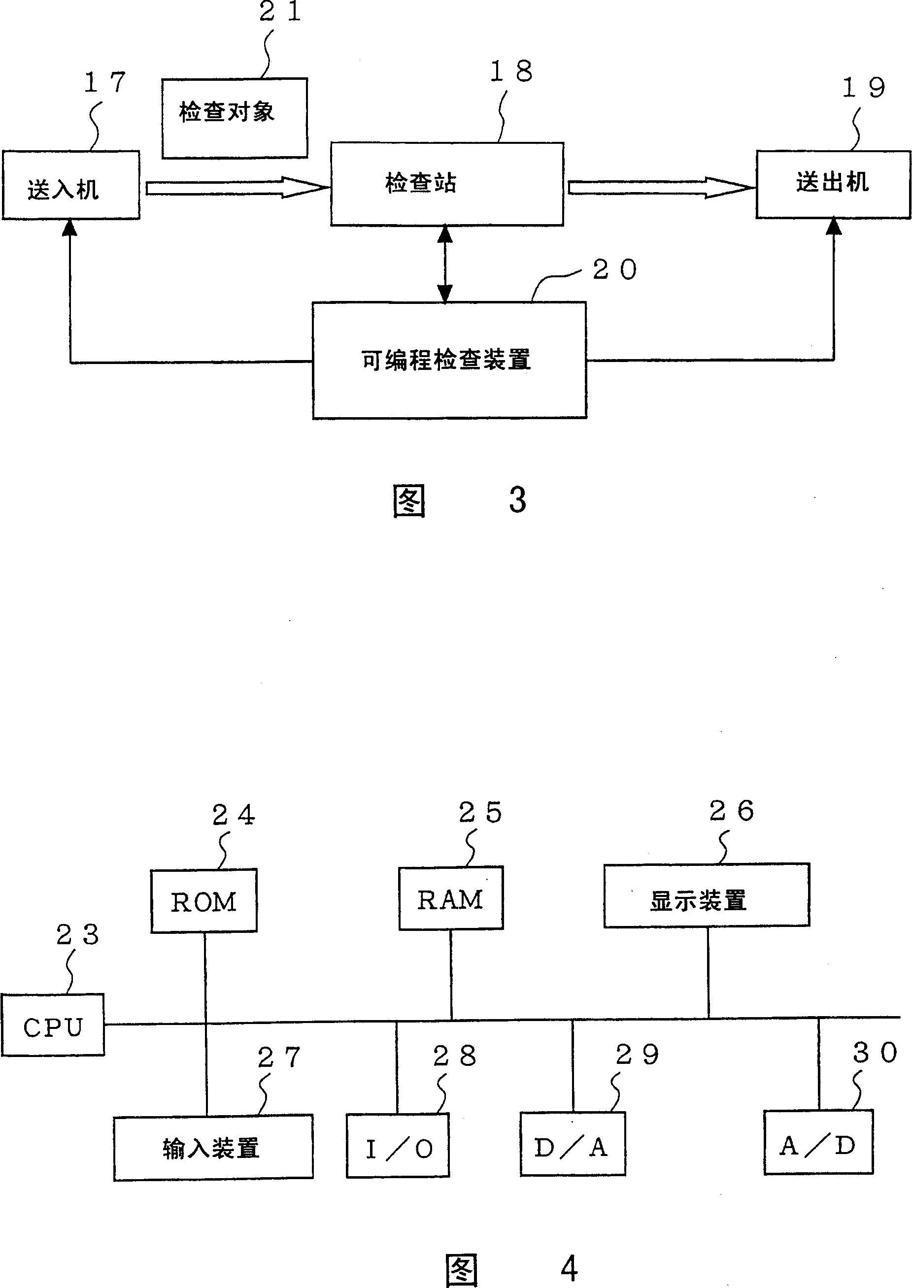
[0052] FIG. 1 is a diagram illustrating a display example of a programming device according to Embodiment 1 of the present invention. FIG. 2 is a diagram illustrating a program writing apparatus according to Embodiment 1. FIG. 3 is a block diagram showing a programmable inspection device that can be used by the programming device of the first embodiment. 4 is a block diagram showing the configuration of the programmable inspection apparatus according to the first embodiment. Throughout the drawings, the same symbols denote the same or equivalent parts.
[0053] In FIG. 3 are shown the feeder 17 , the inspection station 18 , the feeder 19 and the programmable inspection device 20 that controls them. When the inspection is carried out, the programmable inspection device 20 controls the feeder 17 to feed the inspection object 21 to the inspection station 18 . The inspection station 18 attaches a jig to the inspection object 21, electrically connects the inspection object 21 to...
Embodiment approach 2
[0096] 7 and 8 are diagrams illustrating display examples of the programming device according to the second embodiment. The drawing program applied to a programmable display will be explained as an example. The example in FIG. 7 is in the middle of programming development, and it is an example of a case where it is desired to comment all objects (object 2 and object 3) included in object 1 because the part related to object 1 is not completed. Objects 2 and 3 are not commented out one by one; by setting comment prohibition on Object 1, the setting can be reflected in all objects (Object 2 and Object 3) contained in Object 1. The object on the containing side has a means of setting and reflecting its own settings on all the objects it contains (annotation prohibition setting reflection means), so whether the program developer sets the comment prohibition on the containing side object reflects the containing relationship. .
[0097] Figure 8 shows the opposite situation. In t...
Embodiment approach 3
[0105] 11 is a diagram illustrating a display example of the programming device according to the third embodiment. The setting applied to the table program, especially the setting applied to the table element object, will be described as an example. 11 is an example of a situation where the part involved in the table element (hereinafter referred to as table element, meaning table element object) 22 has not been completed in the middle of programming development, so it is desired to test all table elements except table element 22 immediately. In order to prohibit the comment to the cell 22, the cell 22 to be comment-prohibited is directly set to be comment-prohibited. Since each cell itself has the means 131 for keeping the setting of whether to prohibit comments, the program developer sets whether to prohibit comments in units of cells, that is, the object in Embodiment 1 corresponds to the cell object in Embodiment 1 .
[0106] Since the object of the first embodiment corr...
PUM
 Abstract
Description
Claims
Application Information
 - R&D
- Intellectual Property
- Life Sciences
- Materials
- Tech Scout
- Unparalleled Data Quality
- Higher Quality Content
- 60% Fewer Hallucinations
Browse by: Latest US Patents, China's latest patents, Technical Efficacy Thesaurus, Application Domain, Technology Topic, Popular Technical Reports.
© 2025 PatSnap. All rights reserved.Legal|Privacy policy|Modern Slavery Act Transparency Statement|Sitemap|About US| Contact US: help@patsnap.com