Guide and rotation mechanism for crane hanger

A technology of rotating mechanism and guiding mechanism, which is applied in the direction of load hanging components, transportation and packaging, etc. It can solve the problems of poor operation stability, large swing range, poor vertical lifting guidance, etc., and achieves simplified and larger guiding structure. The effect of good operation space and operation stability

Inactive Publication Date: 2008-04-02
TAIYUAN HEAVY IND
View PDF4 Cites 0 Cited by
  • Summary
  • Abstract
  • Description
  • Claims
  • Application Information

AI Technical Summary

Problems solved by technology

However, there are deficiencies. The main reason is that the center hoisting mechanism of an ordinary bridge crane is adopted. The steel wire rope is wound on a vertical plane. Large, the guidance of the vertical lift is not good, which makes the operation stability poor

Method used


Image

  • Guide and rotation mechanism for crane hanger
  • Guide and rotation mechanism for crane hanger
  • Guide and rotation mechanism for crane hanger

Examples


Embodiment Construction

[0014] The guide and rotation mechanism of the crane spreader of the present invention will be described in detail below in conjunction with the accompanying drawings.

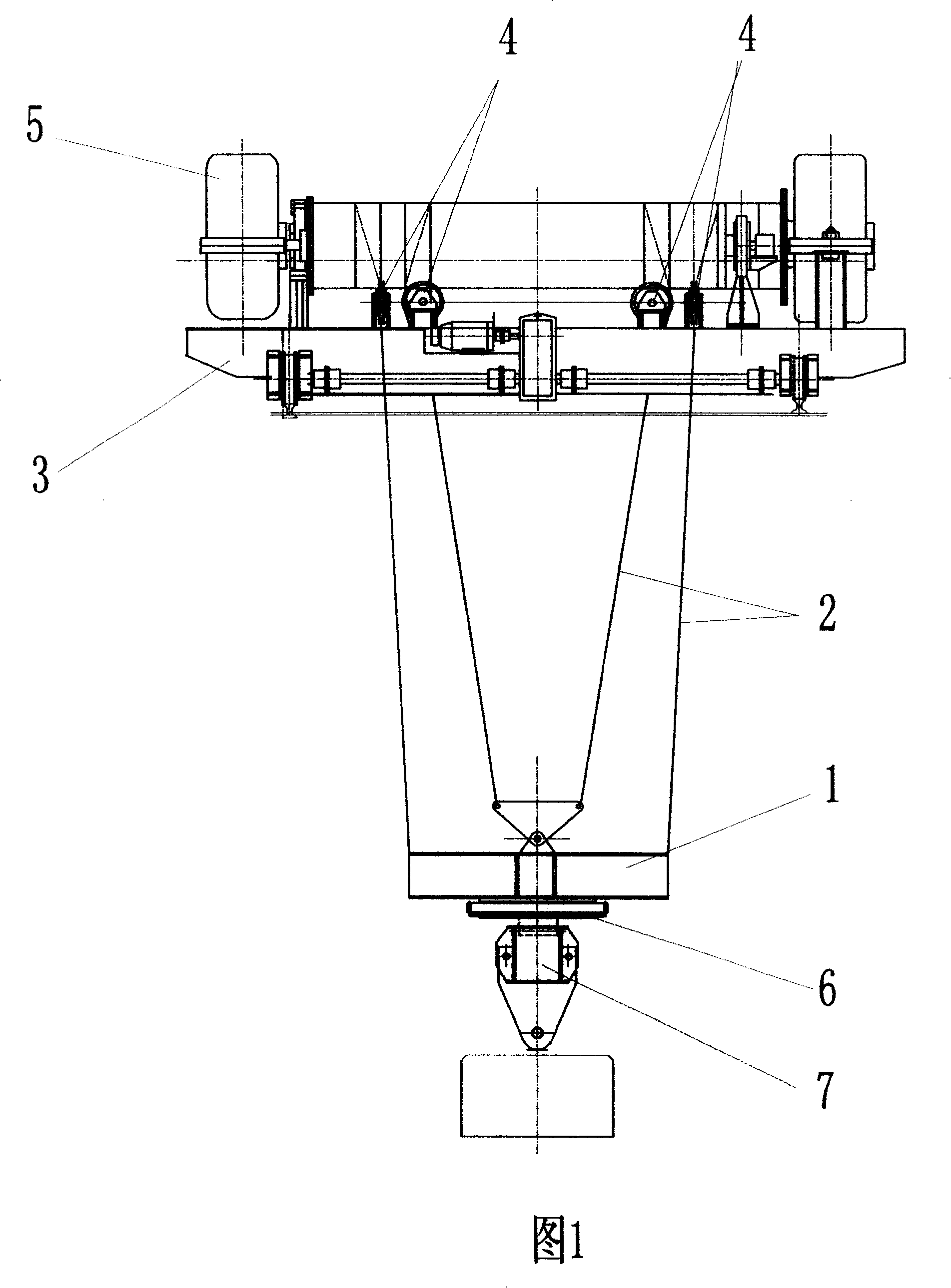
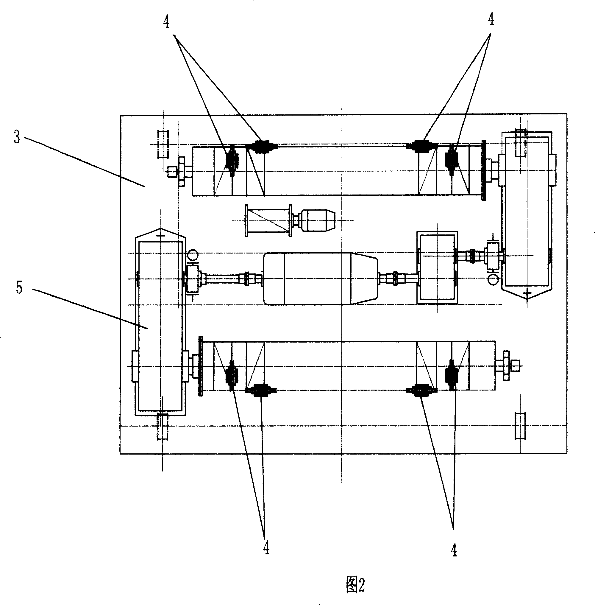
[0015] Figure 1 and Figure 2 show the guiding mechanism of the crane spreader. The guiding mechanism is composed of a cross beam 1 (or called an upper beam), a steel wire rope 2 and a pulley device 4 arranged on a trolley frame 3 . Four pairs of mutually perpendicular pulley devices are arranged on the trolley frame, that is to say, the pulley devices are distributed in a rectangle on the trolley frame, and each corner of the rectangle is provided with two mutually perpendicular pulley devices. The wire ropes that wind down from the pulley device in the hoisting mechanism 5 are connected with four beam ends of the cross beam respectively, forming a cross shape. One end of the steel wire rope is fixed on the reel, and the other end is fixed on the cross beam, so four directions adopt the same fixing method, an...


PUM


Abstract

This invention relates to a guide and rotation machine of lift sling, which comprises guide mechanism, rotation mechanism and crossbeam; it has following peculiarities: a) guide mechanism is formed by cruciform girder, steel rope and block device disposed vertically on the small carriage; b) the steel ropes circling down from the block device of heize mechanism are connected with four girder ends of cruciform girder separately to form a crisscross to position the cruciform girder at parallel and vertical direction; c)the rotation mechanism mounted in the cruciform girder is connected with sling crossbeam.

Description

technical field [0001] The invention belongs to hoisting and transporting machinery, and in particular relates to a guiding and rotating mechanism of a crane spreader. Background technique [0002] The rake cranes used in metallurgical enterprises have been used since the 1950s to rotate the spreader and guide the mechanism in the form of upper trolley, lower trolley, guide frame and spreader. The upper trolley of the crane is equipped with a lifting and tilting mechanism of the spreader, which can realize the lifting of the spreader and the tipping of the material rake. The upper trolley is connected with the lower trolley through a ring track, so as to realize the rotation of the spreader at any angle. It is installed on the guide The guide wheels on the frame guide the tipping action. The lower trolley realizes the movement of the trolley along the span direction. This kind of rake crane has a complex structure, the overall height of the trolley is high, the operating s...

Claims


Application Information

Patent Timeline
Patent Type & Authority Patents(China)
IPC IPC(8): B66C13/08
Inventor 李朗明魏双庆王培红
Owner TAIYUAN HEAVY IND
Why Eureka
Try Eureka