Blazed grating light valve

A grating and projecting light technology, applied in the direction of diffraction grating, optics, optical components, etc., can solve the problems of difficult and expensive manufacturing of light modulators

Inactive Publication Date: 2008-04-02
SILICON LIGHT MACHINES CORP
View PDF5 Cites 0 Cited by
  • Summary
  • Abstract
  • Description
  • Claims
  • Application Information

AI Technical Summary

Problems solved by technology

In addition, these off-axis necks are critical to the operation of the light modulator, so the off-axis necks must have tight tolerances, making the light modulator more difficult and expensive to manufacture

Method used


Image

  • Blazed grating light valve
  • Blazed grating light valve
  • Blazed grating light valve

Examples


Embodiment Construction

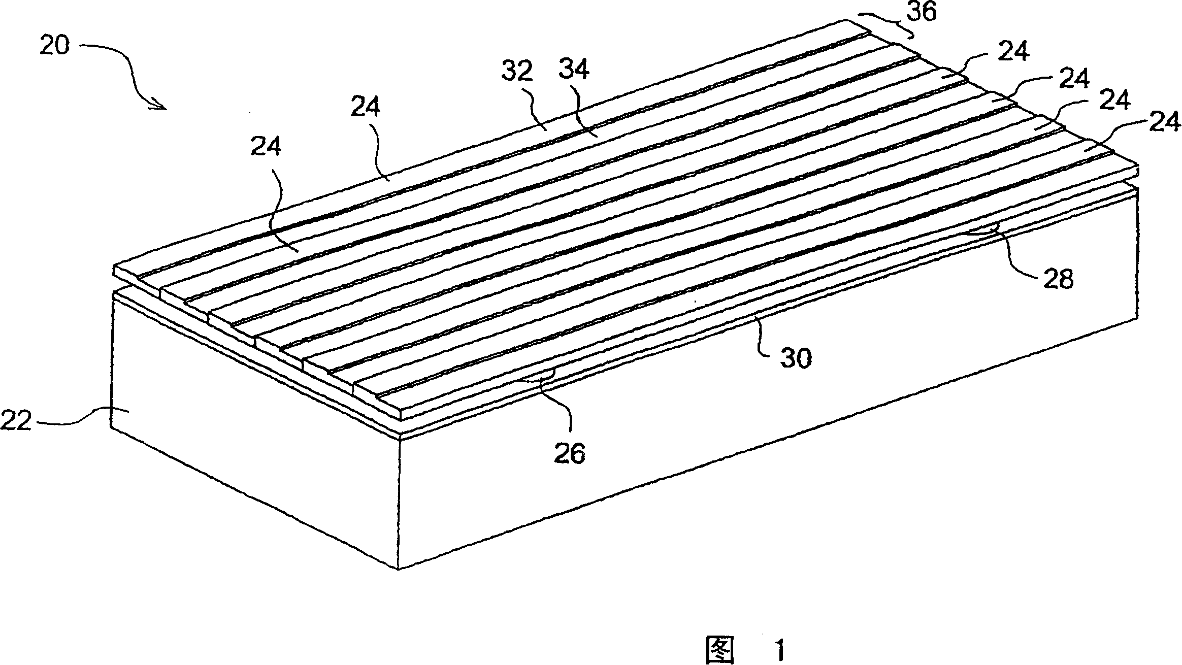
[0029] The preferred light-emitting grating light valve 20 shown in isometric projection in FIG. 1 includes a base 22, elongated members 24, first studs 26 (one shown) and second studs 28 (one shown). Substrate 22 includes a first conductor 30 . Preferably, each elongated member 24 includes a first surface 32 and a second surface 34, both of which reflect light and form a light emitting profile 36 for each elongated member 24. Each elongated member 24 is coupled to the base 22 with a first post cap 26 and a second post cap 28 . Each elongated member 24 is also preferably coupled to base 22 at its first and second ends (not shown).

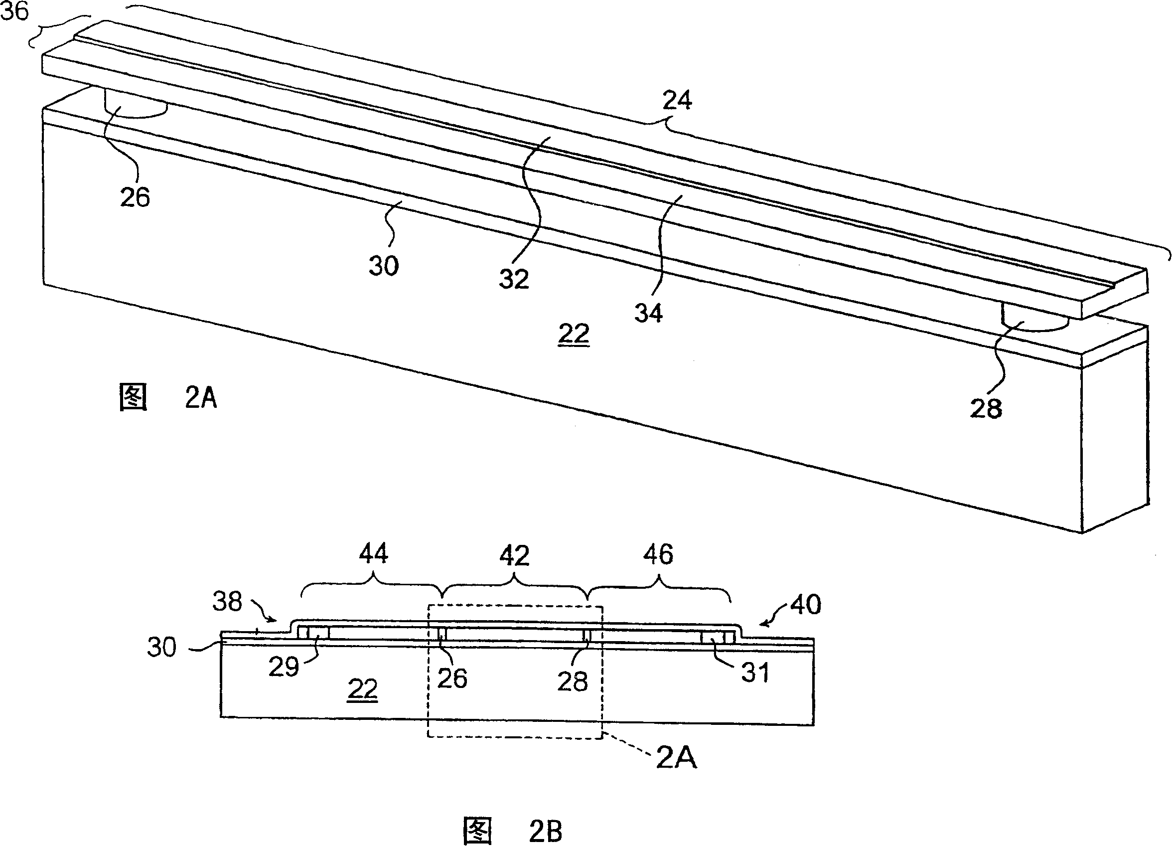
[0030] An elongate member 24 and a portion of base 22 are further shown in isometric projection in FIG. 2A. Elongated member 24 includes first and second surfaces 32 and 34 that both reflect light to form light emitting profile 36 . Elongated member 24 is coupled to the substrate by first and second studs 26 and 28 and is coupled at first and se...


PUM

PropertyMeasurementUnit
thicknessaaaaaaaaaa
thicknessaaaaaaaaaa
thicknessaaaaaaaaaa

Abstract

A light modulator includes elongated elements arranged parallel to each other. In a first diffraction mode, the light modulator operates to diffract an incident light into at least two diffraction orders. In a second diffraction mode, the light modulator operates to diffract the incident light into a single diffraction order. Each of the elongated elements comprises a blaze profile, which preferably comprises a reflective stepped profile across a width. Alternatively, the blaze profile comprises a reflective surface angled at the blaze angle. The elongated elements produce the first diffraction when a first electrical bias is applied between the first conductive elements and a substrate. A relative height of the blazed portions are adjusted to produce the second diffraction. In an alternative embodiment, multiple elongated elements are arranged in groupings, where each of the groupings includes at least three of the elongated elements. When the multiple elongated elements are at a first height, the incident light reflects from the elongated elements. When relative heights of the multiple elongated elements are adjusted by applying individual electrical biases between the first conductive elements and the substrate, the incident light diffracts into the single diffraction order.

Description

technical field [0001] The present invention relates to the field of light modulators, in particular to the field of light modulators in which projected light is modulated to produce luminous diffraction. Background technique [0002] Bloom et al. in US Patent No. 5,311,360 entitled "Method and Apparatus for Modulating Beams" teach a grating light valve capable of operating in reflective and diffractive modes. The grating light valve includes elongated elements suspended above a substrate. In the reflective mode, the multiple surfaces of the grating light valve structurally combine projected light to form reflected light. In the diffractive mode, some of the reflective surfaces of the grating light valve are separated from each other by a quarter wavelength of the projected light to produce diffracted light. At this time, the grating light valve mainly diffracts the light into a positive one diffraction sequence and a negative one diffraction sequence, but also diffracts a...

Claims


Application Information

Patent Timeline
Patent Type & Authority Patents(China)
IPC IPC(8): G02B26/00G02B5/18B29D11/00G02B26/08
CPCG02B26/0808G02B5/18
Inventor D·T·阿姆J·特里斯纳迪J·亨特C·古德曼D·马赫斯瓦里
Owner SILICON LIGHT MACHINES CORP
Why Eureka
Try Eureka