
Spectrometer using MOEMS movable blazed grating array

A technology of blazed gratings and spectrometers, which is applied to the use of diffraction elements to generate spectra, spectrum surveys, and spectrum generation. It can solve the problems of long-term reliability limitations, bulky size, and high signal-to-noise ratio of instruments online, and improve light energy utilization. High measurement sensitivity and the effect of improving the signal-to-noise ratio

Inactive Publication Date: 2010-03-10
CHONGQING UNIV
View PDF0 Cites 16 Cited by
  • Summary
  • Abstract
  • Description
  • Claims
  • Application Information

AI Technical Summary

Problems solved by technology

However, due to the existence of the moving mirror, the long-term online reliability of the instrument is limited. In addition, there are strict requirements on the use and placement environment of the instrument, which is expensive and bulky; array detection type: the array detection side instrument has a fixed optical path and no moving parts. , high measurement accuracy, good reliability, and relatively high signal-to-noise ratio
But there is also the problem that the near-infrared detection array is extremely expensive and the user range is small; acousto-optic tuning type: it is a tuning technology that uses the interaction of ultrasonic waves and specific crystals to generate light
Programmable wavelength control makes it more flexible, but the resolution is relatively low and the price is expensive
[0003] To sum up, traditional spectrometers are large in size, complex in structure, limited in use environment, and expensive, which can no longer meet the requirements of on-site detection and real-time monitoring

Method used


Image

  • Spectrometer using MOEMS movable blazed grating array

Examples


Embodiment Construction

[0020] Preferred embodiments of the present invention will be described in detail below.

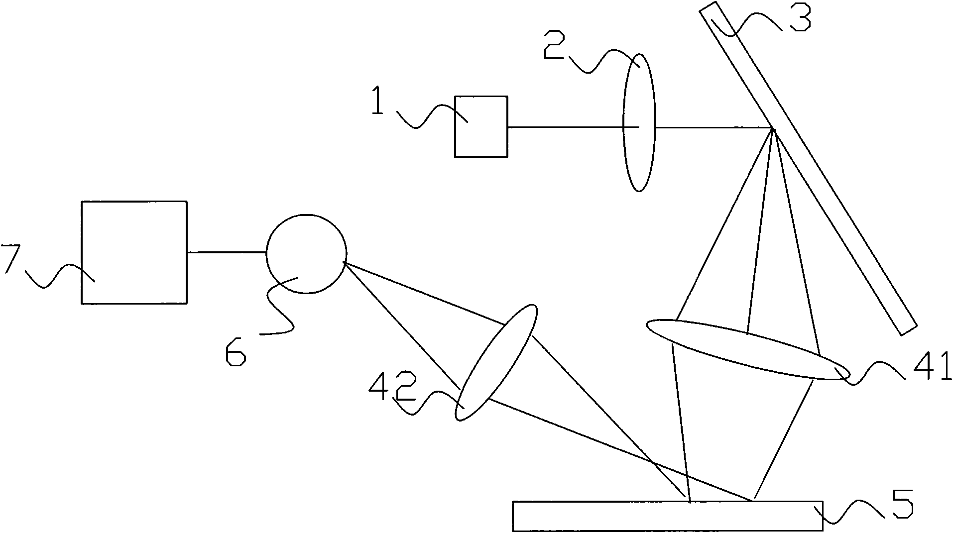
[0021] see figure 1 , the spectrometer using MOEMS movable blazed grating array in this embodiment includes light source 1 , collimation device 2 , grating 3 , imaging device, MOEMS movable blazed grating array 5 and its driving circuit and single point detector 6 .

[0022] The collimating device 2 may use a collimating lens or other collimating devices for parallelizing the light beams from the light source.

[0023] The grating 3 can be a plane reflective grating, a concave grating or a blazed grating to receive the collimated light beam and disperse the light beam; the grating 3 can also be replaced by a prism.

[0024] One or more imaging devices can be set as required. In this embodiment, the first imaging lens 41 is used to image the dispersed light beam onto the MOEMS movable blazed grating array 5, and the second imaging lens 42 is used to image the MOEMS movable blazed grating...


PUM


Abstract

The invention provides a spectrometer which has small volume, simple structure and low cost and uses an MOEMS movable blazed grating array. The spectrometer comprises a light source, a collimating device, a grating or a prism, an imaging device, an MOEMS movable blazed grating array and a driving circuit thereof, and a detector, wherein the collimating device parallels the light beams coming fromthe light source; the grating or the prism receives and disperses the light beams; the imaging device images the dispersed light beams on the MOEMS movable blazed grating array and diffracts the MOEMSmovable blazed grating array to obtain a light beam, and then images the obtained light beam to the detector; the MOEMS movable blazed grating array and the driving circuit thereof are used for diffracting the dispersed light beam; and the MOEMS movable blazed grating array comprises a plurality of parallel MOEMS movable blazed gratings which can be grouped for deflection motion under the controlof the driving circuit so as to gate light beams of different bands. The spectrometer has the advantages of high luminous flux, high light energy utilization rate, high signal-to-noise ratio and thelike, can be widely used in the fields of biochemical analysis, food safety monitoring, etc.

Description

technical field [0001] The invention relates to a MOEMS grating spectrometer. Background technique [0002] At present, there are relatively mature spectrometers on the market, mainly including filter type, raster scanning type, Fourier transform type, array detection type, acousto-optic tuning type, etc., but each has its own advantages and disadvantages. Filter type: simple structure, low cost, large luminous flux, and durable; but poor flexibility, low resolution, single detection object, only suitable for special purposes; grating scanning type: through the rotation of the grating, the monochromatic light is separated by wavelength High and low are sequentially passed through the sample into the detector. This kind of spectroscopic technology is mature and widely used; due to the mechanical wear of the scanning mechanism of this instrument, its wavelength measurement accuracy and reproducibility are poor, and the measurement time of the full spectrum is long; Fourier tr...

Claims


Application Information

Patent Timeline
IPC IPC(8): G01J3/28G01J3/18
Inventor 张智海莫祥霞王伟郭媛君
Owner CHONGQING UNIV
Learn More