Method for producing convex double blazed grating

A technology of blazed grating and convex surface, applied in the field of preparation of diffractive optical elements, can solve problems such as large difficulties, and achieve the effect of ensuring the consistency of grating period and orientation

Active Publication Date: 2010-08-11
SUZHOU UNIV
View PDF4 Cites 19 Cited by
  • Summary
  • Abstract
  • Description
  • Claims
  • Application Information

AI Technical Summary

Problems solved by technology

For the holographic ion beam etching method, it is more difficult to realize the dual blazed grating structure on the convex substrate because the blaze angle is dependent on the groove shape of the grating mask

Method used


Image

  • Method for producing convex double blazed grating
  • Method for producing convex double blazed grating
  • Method for producing convex double blazed grating

Examples


Embodiment 1

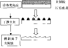
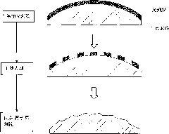
[0053] Embodiment 1: A method of making a convex double blazed grating with a grating period of 5 microns and two blaze angles of 4° and 8° respectively, wherein the diameter of the convex substrate is 40 mm; the radius of curvature is 80 mm, and two interferences are used Exposure, two ion beam etching methods to achieve. The process of fabricating convex blazed gratings by holographic ion beam etching can be found in the appendix figure 2 shown.

[0054] In this embodiment, the production of the convex double blazed grating comprises the following steps: (rectangular photoresist grating mask)

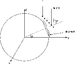
[0055] (1) Coating photoresist on the convex substrate, according to the requirements of the double blazed grating that needs to be made, that is, the grating period (Λ) is 5 microns, and the two blaze angles are 4° and 8° respectively. According to the empirical formula of blaze angle θs and groove shape and ion beam incident angle, θs≈α-3°.

[0056] See attached Figure 5 shown...

Embodiment 2

[0071] Embodiment 2: The grating period of the convex double blazed grating produced in this embodiment is 1000 nanometers, and the two blaze angles are 10° and 25° respectively, wherein the diameter of the convex substrate is 50 mm; the radius of curvature is 100 mm, and two Interference exposure, two ion beam etching methods realize, comprising the following steps: (triangular photoresist grating mask, see attached Figure 7 shown)

[0072] (1) Coating photoresist on the quartz substrate, according to the requirements of the double blazed grating that needs to be made, that is, the grating period (Λ) is 1000 nanometers, and the two blazed angles are 10° and 25° respectively. According to the empirical formula of blaze angle θs and groove shape and ion beam incident angle, θs≈α-3°.

[0073] Taking the triangular photoresist grating as an example, first make a 10° blaze angle (A blaze angle) grating, the general duty ratio f=a / Λ=0.5, by the formula tgα = ...

Embodiment 3

[0085] Embodiment 3: A method of making a holographic double blazed grating with a grating period of 1000 nanometers and two blaze angles of 12 degrees and 25 degrees respectively, wherein the diameter of the convex substrate is 40 mm; the radius of curvature is 90 mm, and two interferences are used Exposure, twice ion beam etching method realizes, comprise the following steps: (sinusoidal photoresist grating mask, see appendix Figure 8 shown)

[0086] (1) Coating photoresist on the quartz substrate, according to the requirements of the double blazed grating that needs to be made, that is, the grating period (Λ) is 1000 nanometers, and the two blazed angles are 12° and 25° respectively. According to the empirical formula of blaze angle θs and groove shape and ion beam incident angle, θs≈α-3°.

[0087] Taking the sinusoidal photoresist grating as an example, at first make a 12 ° blaze angle (A blaze angle) grating, the duty ratio f=a / Λ=0.5 of the grating, and the profile of t...


PUM


Abstract

The invention discloses a method for producing a convex double blazed grating, which is characterized by comprising the following steps: (1) coating photoresist on a grating substrate; (2) carrying out a first interference lithography to produce a photoresist grating reticle mask corresponding to the requirement of an A blazed angle; (3) forming a triangle blazed grating groove shape by inclining an Ar iron beam to carry out scanning lithography for the grating reticle mask in an A grating area and washing the substrate; (4) coating the photoresist again; (5) shielding a B grating area, utilizing the prepared A grating area to carry out moirefringe alignment, then removing shielding and carrying out a second interference lithography to produce a photoresist grating reticle mask corresponding to the requirement of a B blazed angle; (6) etching the B grating area into a triangle blazed grating groove shape by inclining the Ar iron beam to carry out scanning lithography; and (7) washing the substrate to obtain the convex double blazed grating. The invention realizes the production of the convex double blazed grating and can accurately and respectively control the two blazed angles.

Description

technical field [0001] The invention relates to a preparation method of a diffractive optical element, in particular to a preparation method of a convex double blazed grating. Background technique [0002] Grating is a very widely used and important high-resolution dispersive optical element, and it occupies a very important position in modern optical instruments. In 1995, the Italian company Galileo Avioniea replaced the convex mirror in the Offner relay optical system with a convex grating, and developed the world's first convex grating hyperspectral imager system. Since then, the convex grating has become the core device of the imaging spectrometer. [0003] As we all know, the principal maximum direction of diffraction by a single grating is actually not only the geometrical optics propagation direction of light, but also the zero-order direction of the entire multi-slit grating. It concentrates light energy, but cannot separate various wavelengths. In practical applicat...

Claims


Application Information

Patent Timeline
Patent Type & Authority Applications(China)
IPC IPC(8): G02B5/18G03F7/20G02B27/60
Inventor 刘全汪海宾吴建宏胡祖元陈新荣李朝明
Owner SUZHOU UNIV
Why Eureka
Try Eureka