Flow passage sealing of turbine and streamline structure thereof

A turbine and flow channel technology, applied in the field of flow channel structure of steam turbines, can solve the problems of gas power loss, increase radial intrusion flow, increase leakage flow rotor suction effect, etc.

Inactive Publication Date: 2008-04-23
GENERAL ELECTRIC CO
View PDF5 Cites 0 Cited by
  • Summary
  • Abstract
  • Description
  • Claims
  • Application Information

AI Technical Summary

Problems solved by technology

Typical nozzle and blade designs for example for the low pressure section of a steam turbine include a nozzle root diameter equal to the blade root diameter, which results in a very likely upstream facing step under steady state flow conditions which disturbs the fluid flow in the flow channel. streamlined features
A large wheel gap also increases the rotor suction effect of the leakage flow, thereby increasing the radial intrusion flow leading to further aerodynamic losses
In particular, the radial re-entrant flow caused by the rotor suction effect results in fluid flow separation along the flow channel, resulting in aerodynamic losses

Method used


Image

  • Flow passage sealing of turbine and streamline structure thereof
  • Flow passage sealing of turbine and streamline structure thereof

Examples


Embodiment Construction

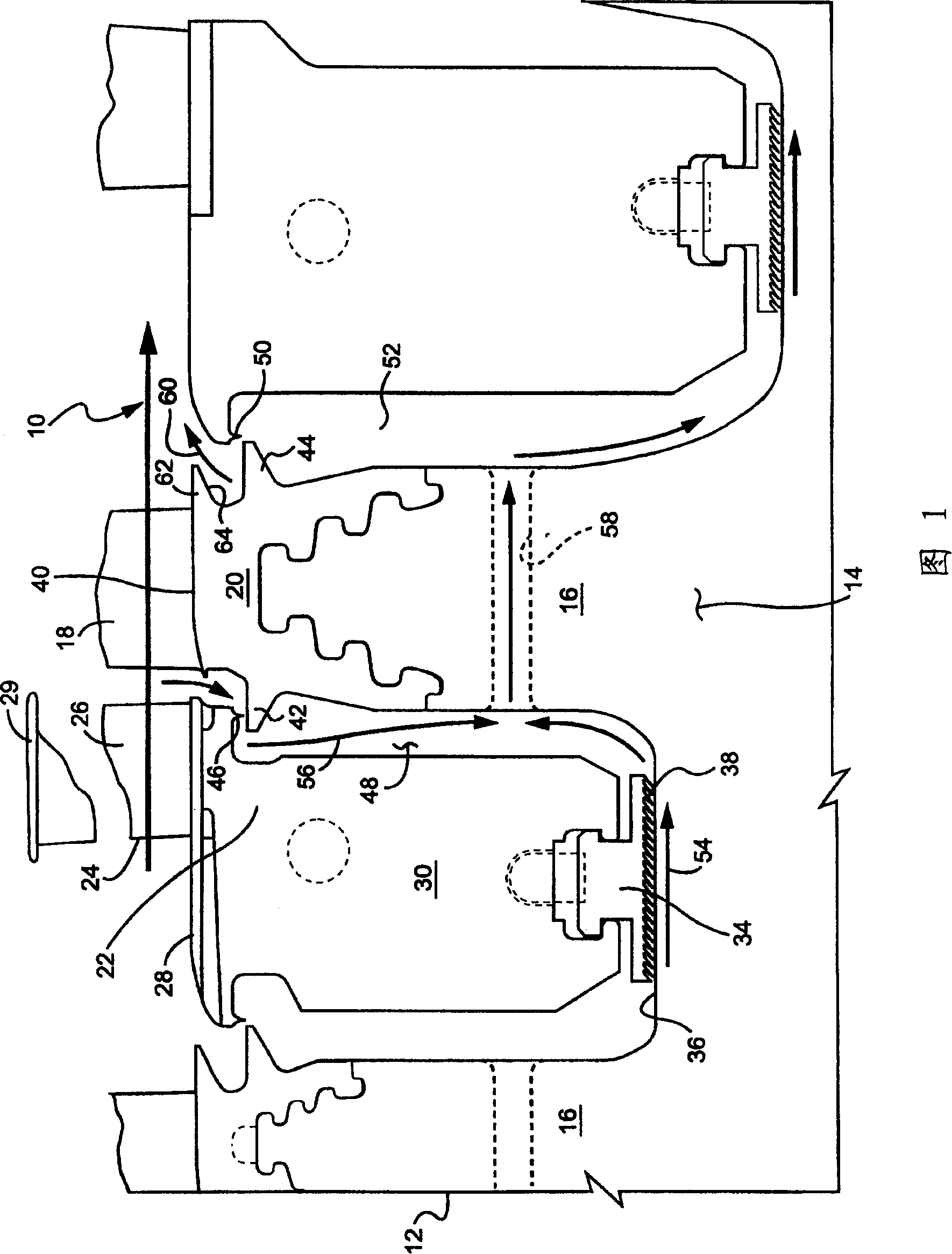
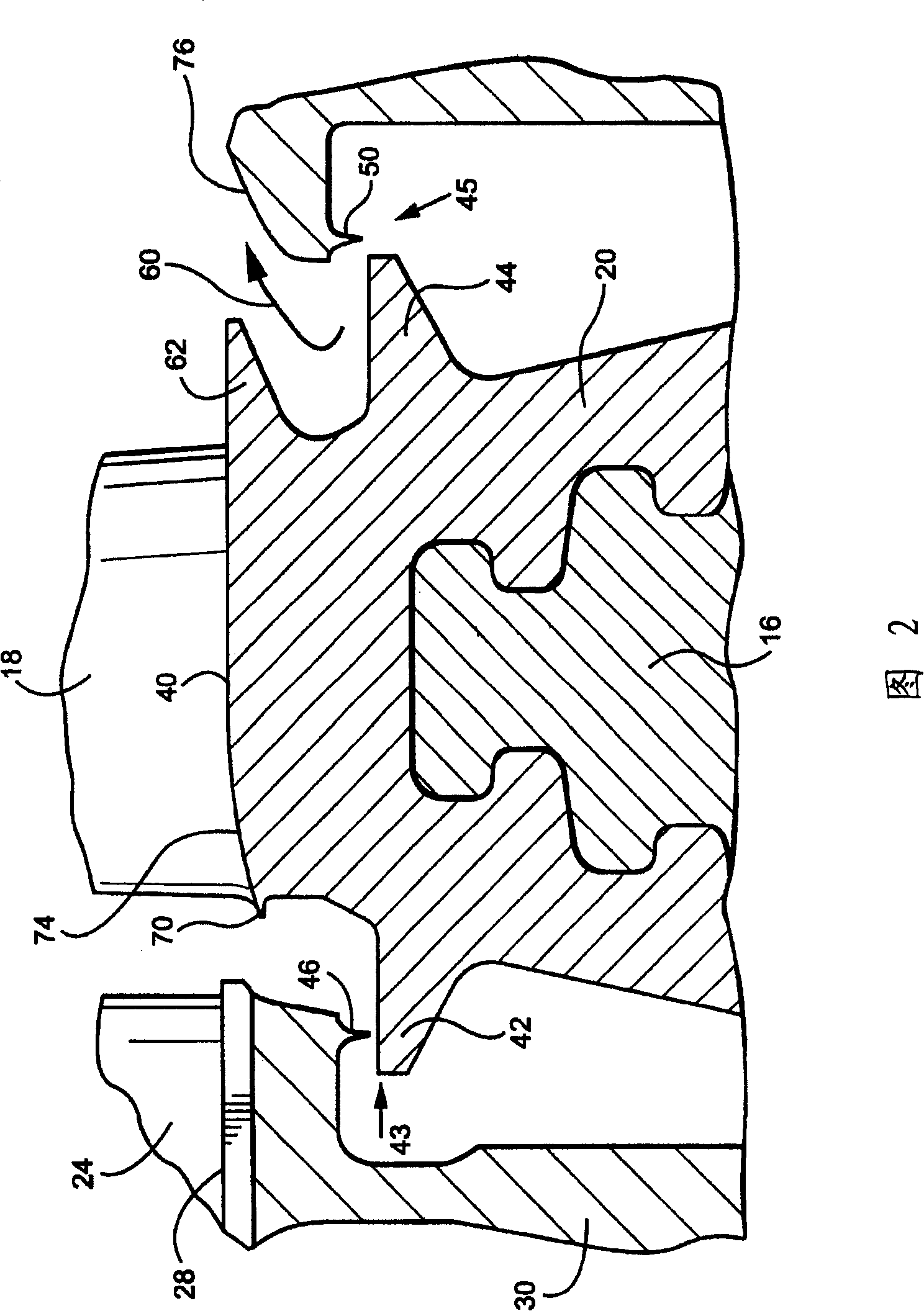
[0012] Referring now to the drawings, and in particular to FIG. 1 , there is shown an interior or root region of the flow path of a turbine 12 , indicated by arrows and generally identified by the reference numeral 10 . An energetic fluid, such as steam, flows along the channel 10 and in the direction of the arrow. The turbine 12 includes a rotor 14 rotatable about a horizontal axis and a plurality of axially spaced rotor wheels 16 each carrying a plurality of circumferentially spaced blades 18 mounted to dovetails at the blade bases. The tail tenon 20 is used to form a tenon connection with the rotor impeller 16 . Also shown in FIG. 1 is a stationary part 22 of the turbomachine comprising an array of axially spaced nozzles 24 . Each array of nozzles 24 has circumferentially spaced stationary airfoils 26 mounted between an inner rim or ring 28 and an outer rim or ring 29 . The nozzle also has an inner web 30 between the rotor wheel and the dovetail 20 of the axially adjacent...


PUM


Abstract

The root region of a flowpath through a turbine includes a sealing configuration for minimizing leakage flow and secondary aerodynamic losses. Entrance and exit root radial seals are provided between upstream and downstream nozzles at locations radially inwardly of the root region of the flowpath to minimize radial leakage flow. To minimize intrusion flow into the flowpath from rotor pumping action and consequent aerodynamic losses, an exit flow guide on each bucket turns the exiting radial flow in a predominantly axial direction. Additionally, the upstream bucket root radius and nozzle root radius are faired or tapered to minimize the possibility of a protuberance projecting into the flowpath at steady state operation. An additional entrance root axial fin is provided on the buckets to reduce the flow coefficient and afford further reduction in leakage flow.

Description

technical field [0001] The present invention relates to a flow path structure for a turbomachine which facilitates streamlined flow characteristics and sealing along the flow path, and more particularly to a flow path structure for a steam turbine which is used to minimize the Leakage flow and secondary gas power loss. Background technique [0002] The flow path through the turbine along the root radius is defined locally by the inner bands or rings of the nozzle and the flow surface along the platform at the blade root of the rotor. Any fluid flow that exits this passage along the root boundary leaks past the vanes and directly reduces the power output of the turbine stage. Typical nozzle and blade designs for example for the low pressure section of a steam turbine include a nozzle root diameter equal to the blade root diameter, which results in a very likely upstream facing step under steady state flow conditions which disturbs the fluid flow in the flow channel. Streaml...

Claims


Application Information

Patent Timeline
Patent Type & Authority Patents(China)
IPC IPC(8): F01D11/00F01D11/02F01D5/08F01D25/00F02C7/28F16J15/447
CPCF01D5/081F01D11/001F01D5/12F01D11/00F01D11/02
Inventor 艾莉森·C·法雷尔道格拉斯·C·霍弗诺曼·D·莱思罗普小雷蒙德·K·奥弗鲍威廉·T·帕里肯尼思·J·罗伯特森
Owner GENERAL ELECTRIC CO
Why Eureka
Try Eureka