Compressor

A compressor and exhaust gas technology, applied in mechanical equipment, machines/engines, liquid variable capacity machinery, etc., can solve problems such as power consumption of fans and unsatisfactory energy saving.

Active Publication Date: 2008-04-23
코벨코컴프레서가부시키가이샤
View PDF5 Cites 0 Cited by
  • Summary
  • Abstract
  • Description
  • Claims
  • Application Information

AI Technical Summary

Problems solved by technology

Without such correspondence, it is impossible to keep the temperature of the exhaust gas at a certain temperature or below a certain temperature. As a result, there is a possibility that a gas that cannot cope with the supply of gas that requires a certain temperature or below a certain temperature may be generated. It is unfavorable to supply the requirements of the destination, and it is unavoidable to consume fan power, which is not ideal from the viewpoint of energy saving

Method used


Image

  • Compressor
  • Compressor
  • Compressor

Examples


Embodiment Construction

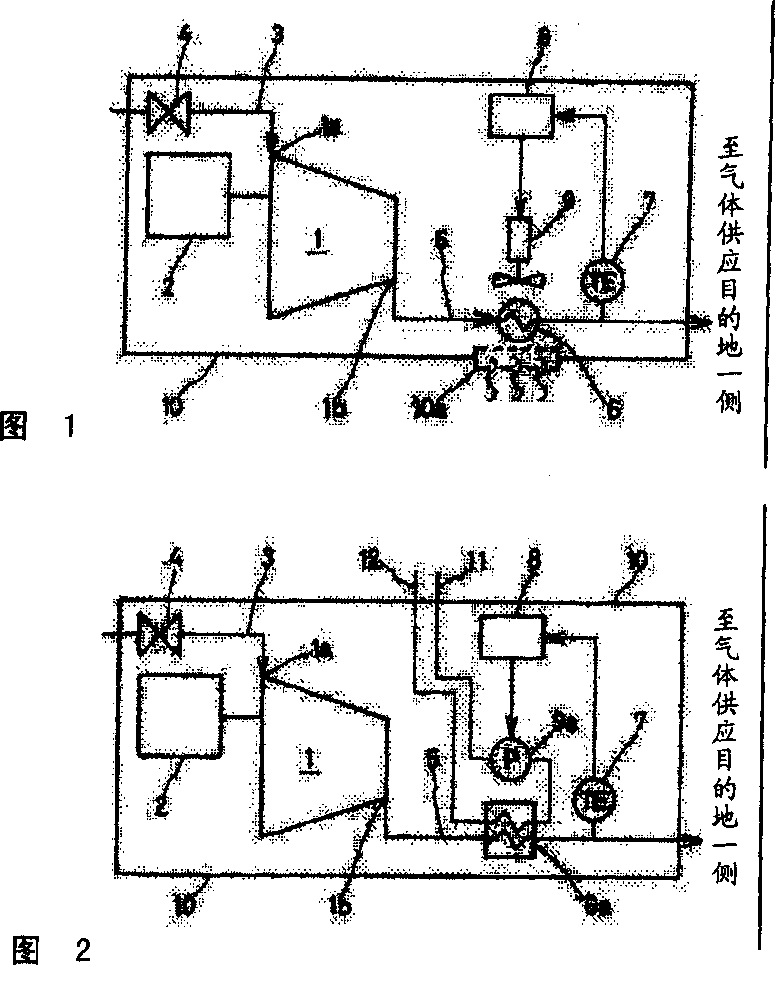
[0031] The compressor according to Embodiment 1 of the present invention will be described as an example in which the compressor is a self-contained compressor and the gas to be compressed is air. FIG. 1 is a schematic system diagram of a self-contained compressor according to Embodiment 1 of the present invention.

[0032] Symbol 1 shown in FIG. 1 is a compressor main body driven by a motor 2, and a suction flow path 3 formed by adding a flow regulating valve 4 to adjust the flow rate of suction air communicates with the suction port 1a of the compressor main body 1. . Furthermore, from the discharge port 1b of the compressor main body 1 to the supply destination side of the compressed and discharged discharge air (discharge gas) not shown in the figure, there is connected a discharge discharge system formed by adding an air-cooled heat exchanger 6 for cooling the discharge air. Flow path 5. On the downstream side of the heat exchanger 6 of the discharge flow path 5, a temp...


PUM


Abstract

The compressor includes the compressor main body compressing suction gas sucked from a suction flow passage, and a discharge flow passage supplying the gas discharged from a discharge port of the compressor main body to a gas supply destination side. The discharge flow passage has a temperature detector detecting a discharged gas temperature, a heat exchanger cooling the discharged gas, and a cooling fan flowing the cooling air against the heat exchanger. A computing unit is provided to control the revolution number of the cooling fan so that the discharged gas becomes a predetermined temperature defined in advance. By the constitution, cooling is properly performed depending on the calorie of the gas discharged from the compressor main body, so as to reduce the required motive power used for the cooling.

Description

technical field [0001] The present invention relates to an improvement of a compressor, and more particularly, to a compressor capable of appropriately cooling the compressed gas according to the heat (temperature, gas volume) of the compressed gas discharged from the main body of the compressor, thereby reducing the power required for cooling. Background technique [0002] As a compressor that cools the compressed gas discharged from the compressor main body through a heat exchanger provided on the discharge flow path of the compressed gas flow and a fan that blows air toward the heat exchanger, and then supplies it to the outside of the machine, for example, there is known A packaged oil-cooled compressor with the structure described below. Hereinafter, an overview of a conventional packaged oil-cooled compressor will be described with reference to the schematic system explanatory diagram of FIG. 6 . [0003] In the case of the self-contained oil-cooled compressor 51 , it...

Claims


Application Information

Patent Timeline
Patent Type & Authority Patents(China)
IPC IPC(8): F04B49/00F04C28/00
Inventor 中村元
Owner 코벨코컴프레서가부시키가이샤
Why Eureka
Try Eureka