

Multi-part roll stand for edgers in rolling mills
A rolling mill stand, multi-piece technology, applied in the direction of metal rolling stand, metal rolling mill stand, metal rolling, etc., can solve the problems of high degree of difficulty, high risk of casting, selection restrictions, etc., to achieve reliable control, Effect of avoiding cracking or vibration, uniform stress distribution
- Summary
- Abstract
- Description
- Claims
- Application Information
AI Technical Summary
Problems solved by technology
Method used
Image

Examples
Embodiment Construction
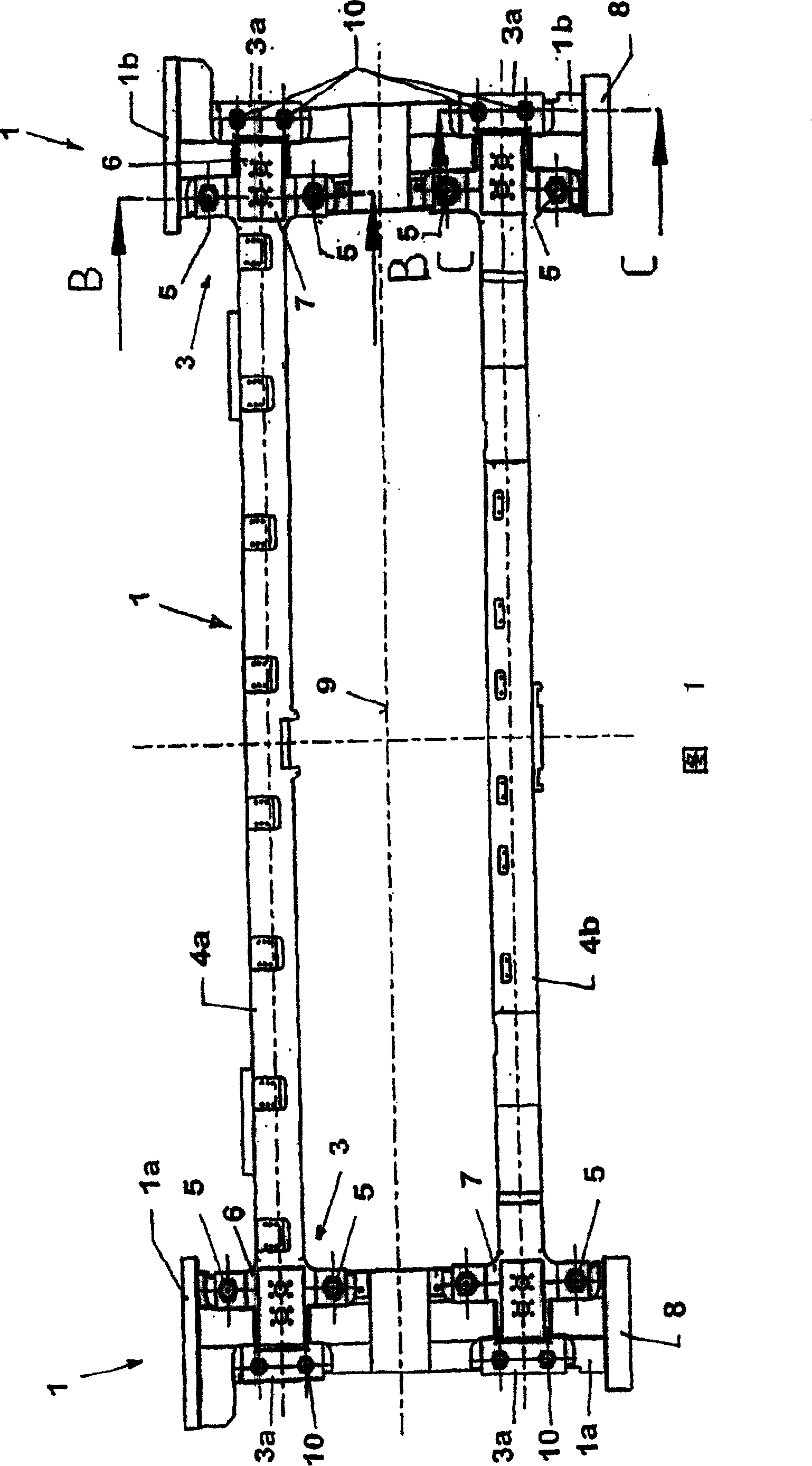
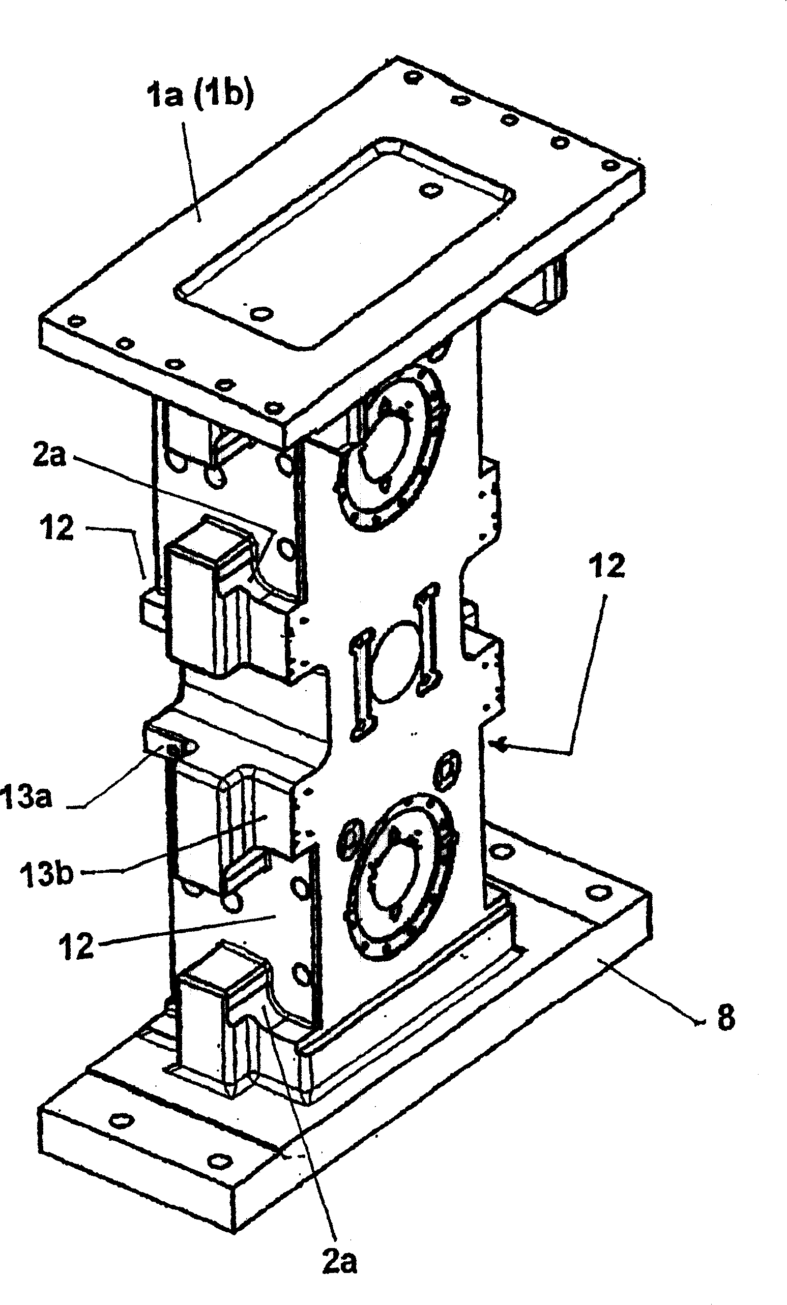
[0034] According to FIG. 1 , the main assembly 1 consists of two transverse beams 1 a and 1 b and four longitudinal beams 4 a and 4 b. At the transition to the transverse beams 1a, 1b, a connection point 3 with a covering part 3a is formed in each case.
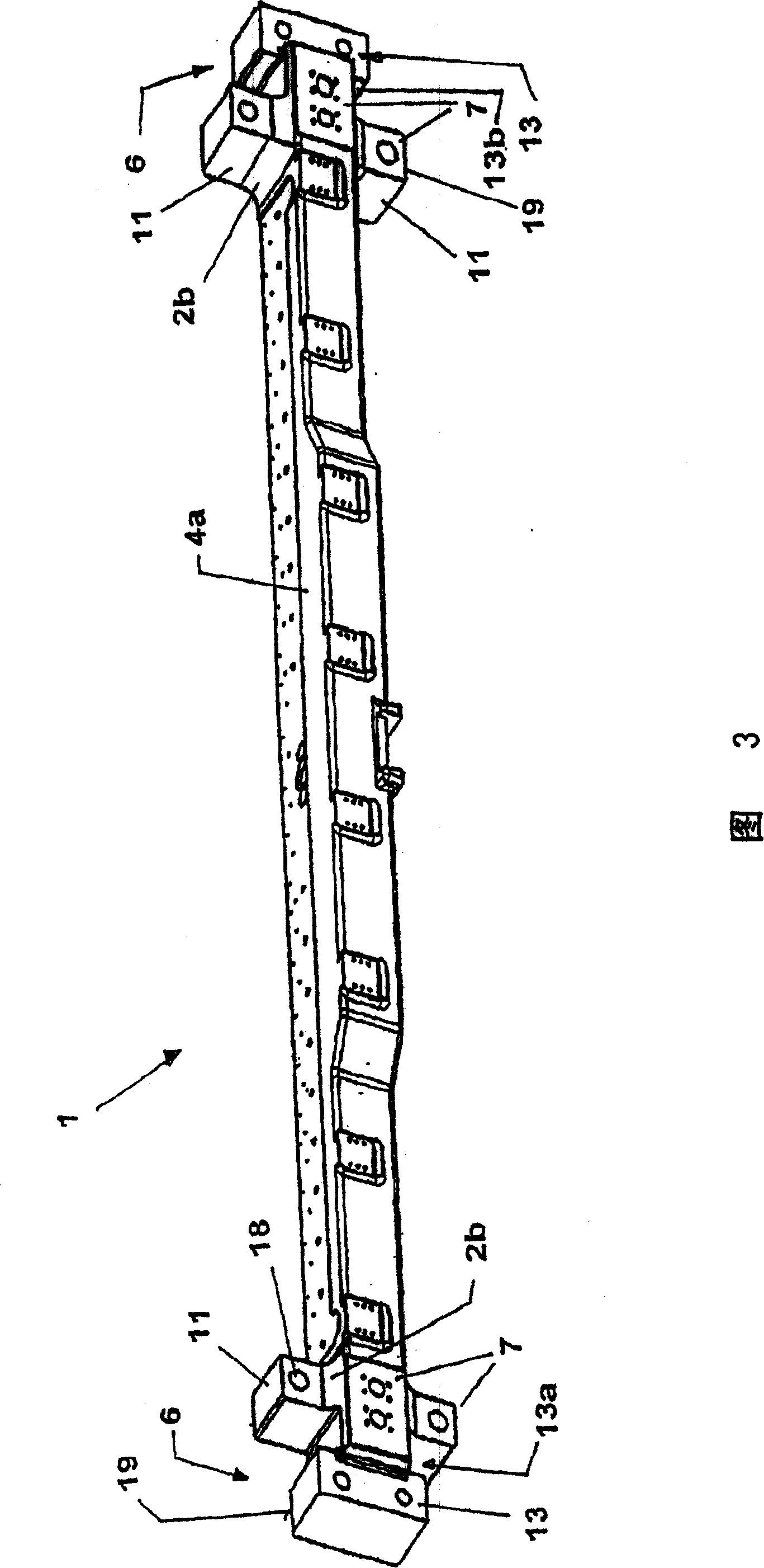
[0035] In the illustrated six-part embodiment of the main assembly 1, which consists of two transverse beams 1a, 1b and four longitudinal beams 4a, 4b, a cross arm 11 or a projection 19 is formed on the respective longitudinal beam end 6. The cruciform 7.
[0036] The connection between the crossbeams 1a, 1b and the longitudinal girders 4a, 4b is realized by means of through-threads 5, wherein the crossbeams and the longitudinal girders are respectively supported on a support plate not shown in detail below the crossbeam base 8, said through-beams being held by Prestressing and thus forming a joint in the material expandable axially and transversely. The longitudinal beam ends 6 are connected via crosses 7 to the transverse...
PUM
 Abstract
Description
Claims
Application Information