Rotary parallel piston compressor

A rotary and compressor technology, applied in the direction of rotary piston machinery, rotary piston pump, rotary piston/swing piston pump components, etc., can solve the problem of increased piston pressure, reduced compressor efficiency, and parts processing Difficulty and other issues

Active Publication Date: 2016-05-11
浙江百达精工股份有限公司
View PDF8 Cites 0 Cited by
  • Summary
  • Abstract
  • Description
  • Claims
  • Application Information

AI Technical Summary

Problems solved by technology

According to the structure, the rotary compressor also has the following defects: 1. In order to prevent the vanes from breaking away from the grooves on the outer peripheral surface of the piston, the required spring force of the spring is relatively large, and the spring stiffness of the rotary compressor spring is estimated to be Should be controlled above 20Kg/㎜
As a result, a series of problems arise: such as the increased pr

Method used


Image

  • Rotary parallel piston compressor
  • Rotary parallel piston compressor
  • Rotary parallel piston compressor

Examples


Embodiment 1

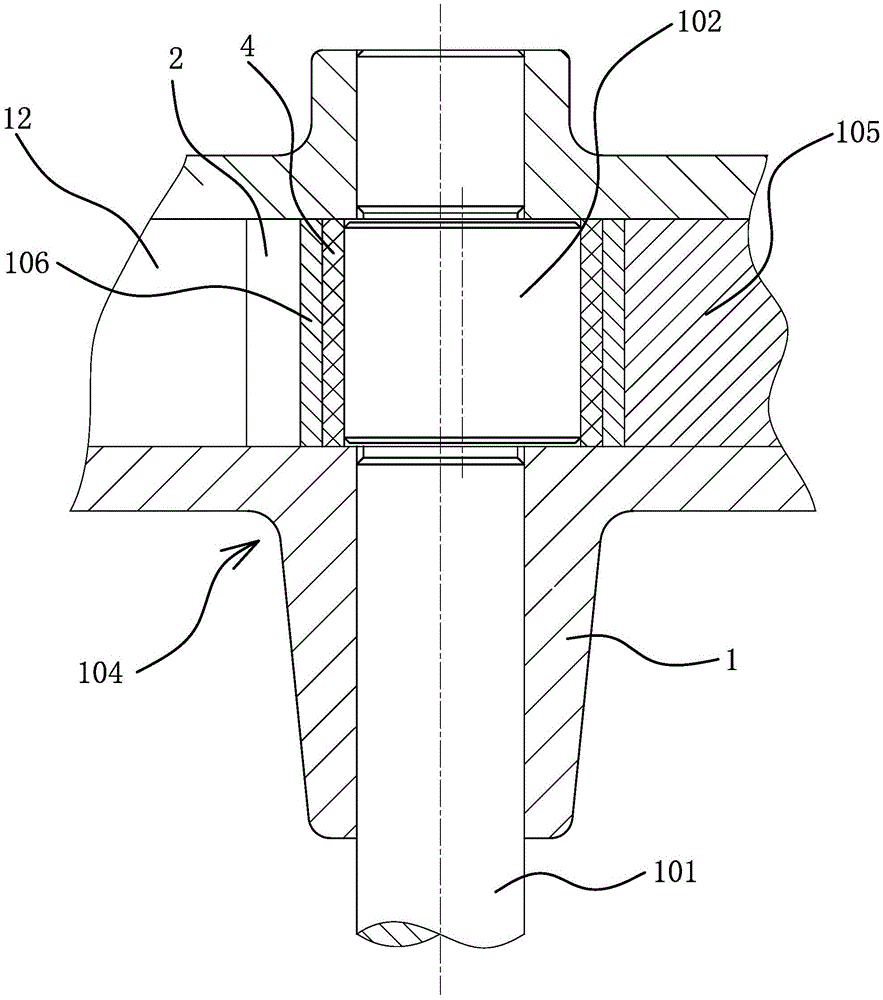
[0040] Such as figure 1 with figure 2 As shown, the rotary translational piston compressor includes a motor 103 , a cylinder 104 , a crankshaft 101 , blades 105 , a piston 106 and a spring 111 .

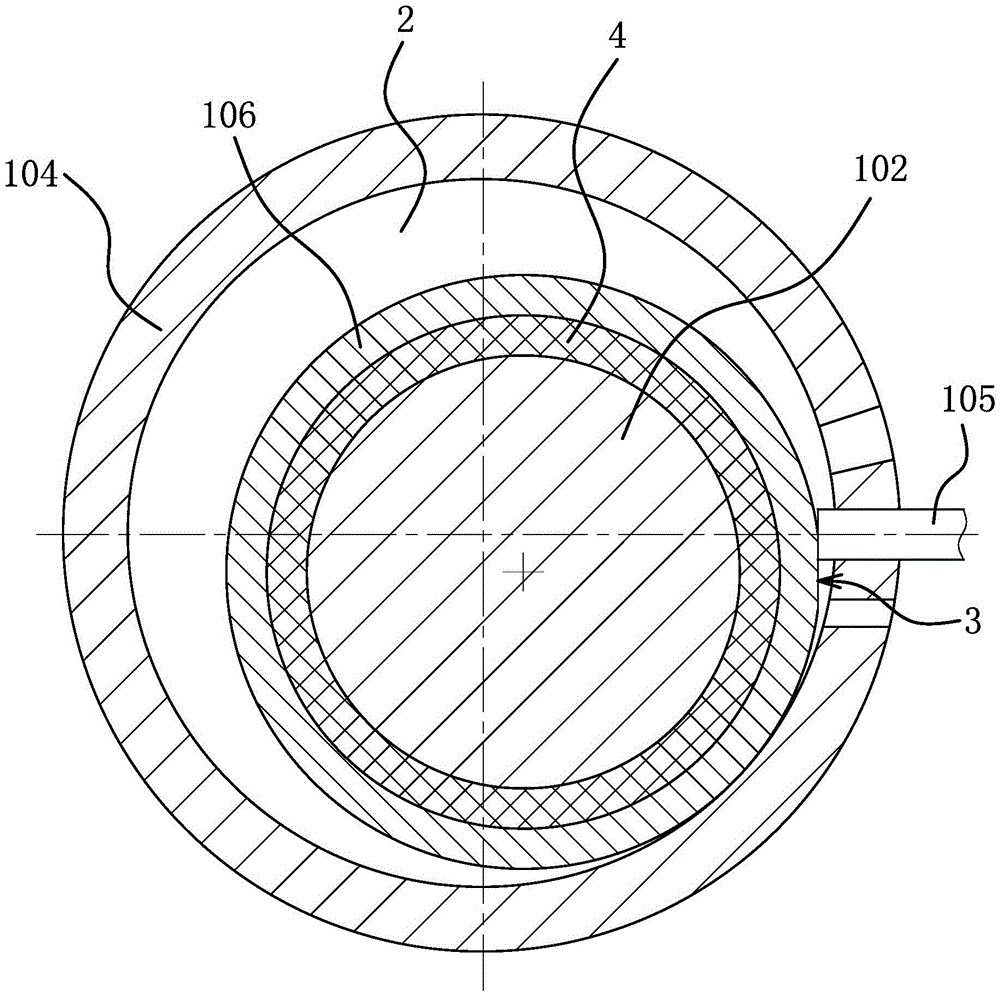
[0041] The cylinder 104 includes a cylinder body 12 and a cylinder head 1 , and a piston chamber 2 and vane grooves are provided in the cylinder 104 .

[0042] The crankshaft 101 has an eccentric portion 102 , the crankshaft 101 passes through the piston cavity 2 of the cylinder 104 , and the eccentric portion 102 is located in the piston cavity 2 . The rotating shaft of the motor 103 is connected with the crankshaft 101 .

[0043] The vane 105 is embedded in the vane slot and can slide along the side wall of the vane slot. The piston 106 is sleeved on the eccentric portion 102 . The spring 111 is located in the vane groove, one end of the spring 111 abuts against the other end of the vane 105 , the other end of the spring 111 abuts against the cylinder 104 , and the spring 111...

Embodiment 2

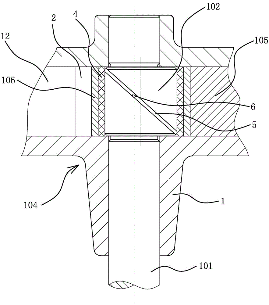
[0049] The structure and principle of this embodiment are basically the same as that of Embodiment 1, the difference is that: image 3 with Figure 4 As shown, in order to further reduce the coefficient of friction between the piston 106 and the eccentric part 102, a first helical groove 5 is provided on the outer surface of the eccentric part 102, and an oil supply passage communicating with the first helical groove 5 is provided in the crankshaft 101. 6. When the rotary translational piston compressor works, lubricating oil enters the gap between the anti-friction sleeve 4 and the eccentric part 102 through the oil supply channel 6 . The provision of the first spiral groove 5 makes it easier for lubricating oil to fill the above-mentioned gaps, that is, to avoid the phenomenon of oil shortage in the above-mentioned gaps during high-speed operation. Supplying lubricating oil in the above-mentioned gap can also take away the heat generated by friction, so as to prevent the a...

Embodiment 3

[0051] The structure and principle of the present embodiment are basically the same as those of the second embodiment, the difference is that: Figure 5 As shown, the rotary translational piston compressor also includes a second helical groove 7 located on the outer surface of the anti-friction sleeve 4, and the anti-friction sleeve 4 is provided with a cavity connecting the second helical groove 7 and the inner cavity of the anti-friction sleeve 4. The first communication hole 8 . That is, lubricating oil enters the gap between the anti-friction sleeve 4 and the piston 106 through the first communication hole 8 ; the second spiral groove 7 makes it easier for the lubricating oil to fill the gap.


PUM


Abstract

The invention provides a rotary translation piston compressor, belonging to the technical field of mechanical engineering. The rotary translation piston compressor solves the problem that the elasticity strength of a spring needed by an existing rotary translation piston compressor is high. The rotary translation piston compressor comprises an air cylinder, a crankshaft and blades, wherein a piston is sleeved on an eccentric part, and a plane part is arranged on the peripheral surface of the piston; springs are arranged between the blades and the air cylinder; the blades prop against the plane part on the peripheral surface of the piston, and the end surfaces of the blades, propping against the piston, are planes; the eccentric part and the piston are connected with each other through a friction reducing mechanism which can enable the end surfaces of the blades to always prop against the plane on the peripheral surface of the piston. Plane friction and plane sealing are adopted between the blades and the piston of the rotary translation piston compressor so as to enlarge the sealing surface, and improve the sealing property. Meanwhile, due to the plane sealing, a high-pressure refrigerant can not enter the parts between the blades and the piston easily, so that the additional force of the high-pressure refrigerant to the moving direction of the blades in the operation of the compressor is reduced.

Description

technical field [0001] The invention belongs to the technical field of mechanical engineering, and relates to a fluid variable displacement machine of a rotary piston, in particular to a rotary translational piston compressor. Background technique [0002] The air conditioner compressor is a driven fluid machine that raises low-pressure refrigerant gas to high pressure. The air conditioner compressor is the heart of the refrigeration system. Rotary piston air conditioner compressors are widely used in household air conditioners. [0003] There are many relevant documents about rotary piston compressors, such as the rotary piston compressor [application number: 97114554.7; publication number: CN1174297A] recorded in Chinese patent literature. In the background art of this document, conventional rotary piston compressors are described, such as Figure 12 with Figure 13 As shown, it includes a crankshaft 101 having an eccentric portion 102 , a motor 103 driving the cranksha...

Claims


Application Information

Patent Timeline
IPC IPC(8): F04C18/356F04C29/00
Inventor 阮吉林张启斌董良玮
Owner 浙江百达精工股份有限公司
Why Eureka
Try Eureka