Method for designing inner mould self-setting digital controller

A digital controller, internal model controller technology, applied in the direction of adaptive control, general control system, control/regulation system, etc., can solve the problems of adjusting the performance of the controller parameter system, ignoring the identification method test signal design, inability to know and so on

Inactive Publication Date: 2008-04-30
SHANGHAI JIAOTONG UNIV
View PDF4 Cites 0 Cited by
  • Summary
  • Abstract
  • Description
  • Claims
  • Application Information

AI Technical Summary

Problems solved by technology

[0002] In 1979, the internal model control structure (IMC) was first proposed by Brosilow based on Smith's predictive compensation control principle, and then Carcia and MorariGarcia proposed a unified basic structure starting from the typical single-input single-output system block diagram, the internal model Control technology has been applied in many industrial control processes, and it is recognized as one of the most suitable advanced control methods for industrial practical applications. However, there are three difficulties in the current application: When engineers and technicians apply traditional manual tuning controllers It is impossible to know how to effectively and quickly adjust the controller parameters to achieve a compromise between system performance and robustness. How to adjust and improve the robust stability and nominal output response in the industrial control process is also a current control problem. How to effectively The application of internal model control technology to large time-delay systems has not been completely resolved.
[0003] It should be pointed out that since most of the current research focuses on parameter estimation and convergence analysis, and ignores the test signal design in the identification method, the research on test experiments and model validity verification is precisely the combination with practical applications. the closest aspect

Method used


Image

  • Method for designing inner mould self-setting digital controller
  • Method for designing inner mould self-setting digital controller
  • Method for designing inner mould self-setting digital controller

Examples


Embodiment Construction

[0047] The technical solutions of the present invention will be further described below in conjunction with the accompanying drawings and embodiments.

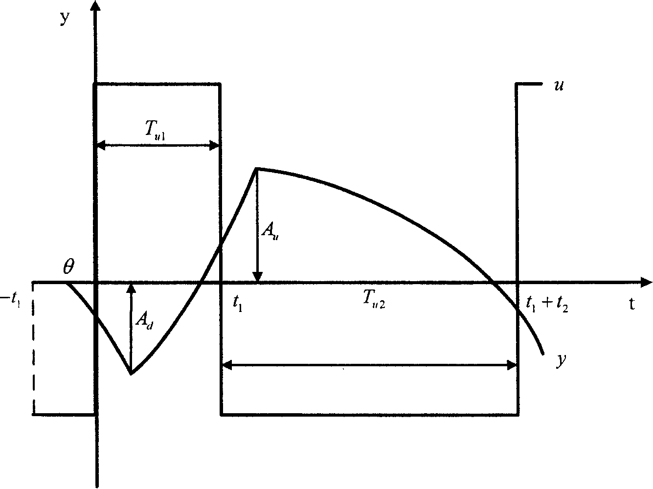
[0048] Such as figure 1 As shown, it means that under the action of the bias relay, the input signal of the object to be identified is a periodic square wave as shown in the figure, and the corresponding periodic signal is output.

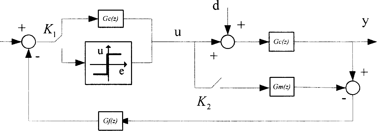
[0049] Such as figure 2 As shown, it represents the control block diagram of the present invention applied in the production process, and the control system operates according to the opening and closing of the two toggle keys.

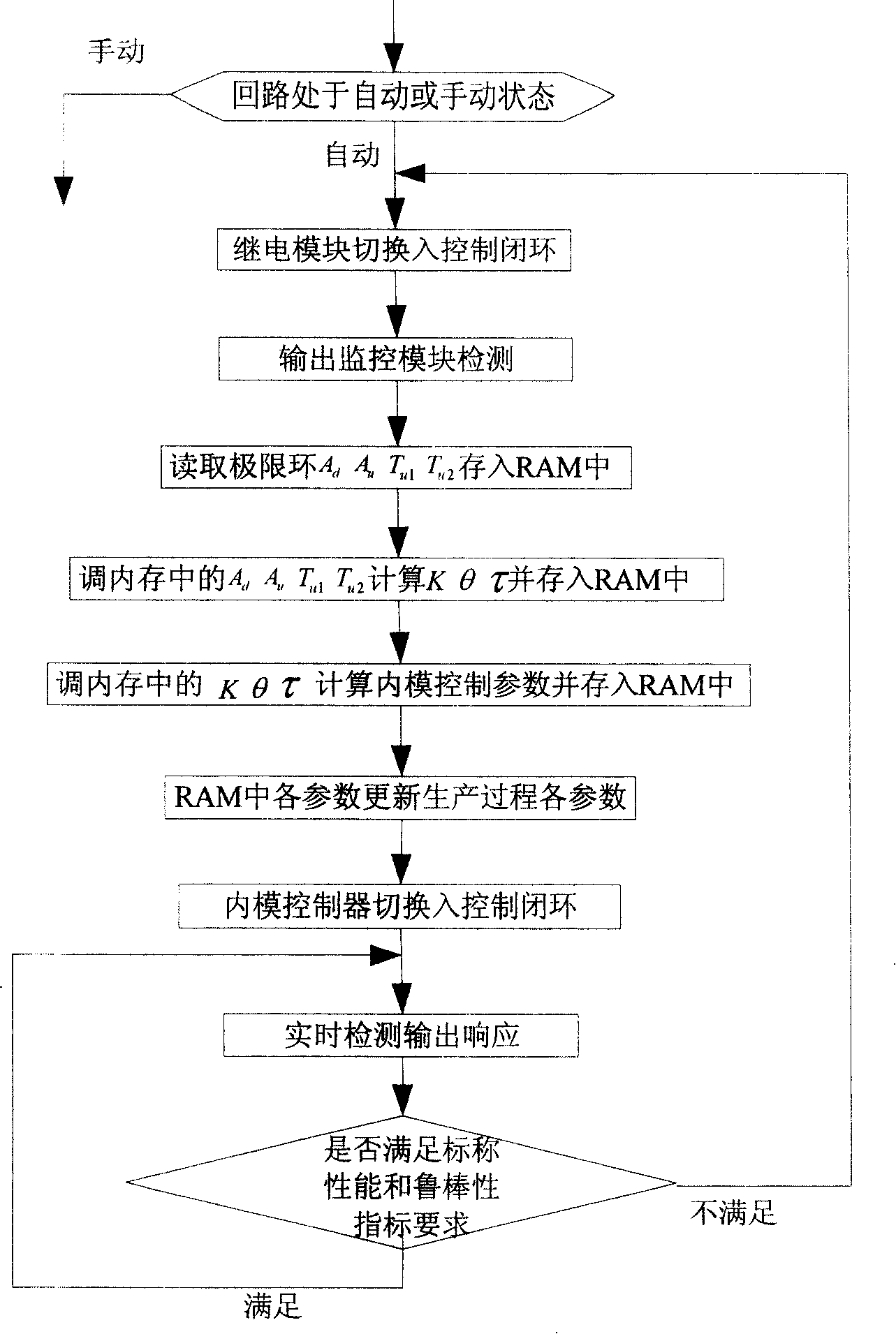
[0050] Such as image 3 Shown is the flow chart of the method of the present invention, and the whole system operates according to this flow.

[0051] As shown in Figure 4, the system is mainly composed of an operation console, a host computer, an output console and an output monitoring module. The operation control platform is the user interface, where engineers and t...


PUM


Abstract

The present invention adopts single-order plus dead-time model; said upper computer controlling output panel control board key to make systems operation on ' identifying stage ', at this point, the relay identifying link switched into closed loop system; under action of relay link, after beginning systems operation, at short notice establishing limit loop; according to real-time measurement to relay output each parameter and biasing relay feed-back identifying formulae to calculate out system identifying three parameters: K, Theta and Pi, and storing in RAM. According to identified model parameter, system calculates each parameter of novel internal mold controller, computational result stored in RAM memory unit, the obtained model and internal mold controller parameter loading in each link in real production process. The present invention realizes the self calibration of digit internal mold controller, reducing hardware cost and raising systematical mobility, reliability and accuracy.

Description

technical field [0001] The invention relates to a method in the technical field of industrial process control, in particular to a design method of an internal model self-tuning digital controller. Background technique [0002] In 1979, the internal model control structure (IMC) was first proposed by Brosilow based on Smith's predictive compensation control principle, and then Carcia and MorariGarcia proposed a unified basic structure starting from the typical single-input single-output system block diagram, the internal model Control technology has been applied in many industrial control processes, and it is recognized as one of the most suitable advanced control methods for industrial practical applications. However, there are three difficulties in the current application: When engineers and technicians apply traditional manual tuning controllers It is impossible to know how to effectively and quickly adjust the controller parameters to achieve a compromise between system p...

Claims


Application Information

Patent Timeline
Patent Type & Authority Patents(China)
IPC IPC(8): G05B13/04
Inventor 王萍张卫东顾诞英赵青王伦
Owner SHANGHAI JIAOTONG UNIV
Why Eureka
Try Eureka