Laser spot coating-shaping process and coaxial spray head
A molding process and coaxial nozzle technology, which is applied in the field of laser processing, can solve the problems of inconvenient spot cladding of single-layer tubes, achieve the effects of reducing quality defects, reducing step effects, and improving productivity
Inactive Publication Date: 2008-05-14
SUZHOU UNIV
View PDF11 Cites 0 Cited by
- Summary
- Abstract
- Description
- Claims
- Application Information
AI Technical Summary
Problems solved by technology
But the powder feeding tube of this invention is a bent single-layer tube, which is inconvenient to realize spot-changing cladding
Method used
View moreImage
Smart ImageViewing Examples
Examples
Embodiment 1
[0033] In the first embodiment, the specification of the powder feeding pipe is changed. Layer profile cladding process parameters: small-diameter tube powder feeding, powder spot diameter 1.8mm, light spot diameter 1.7mm; layer internal area cladding process parameters: large-diameter tube powder feeding, powder spot diameter 9mm, light spot diameter 8mm .
Login to View More PUM
| Property | Measurement | Unit |
|---|---|---|
| diameter | aaaaa | aaaaa |
| diameter | aaaaa | aaaaa |
| diameter | aaaaa | aaaaa |
Abstract
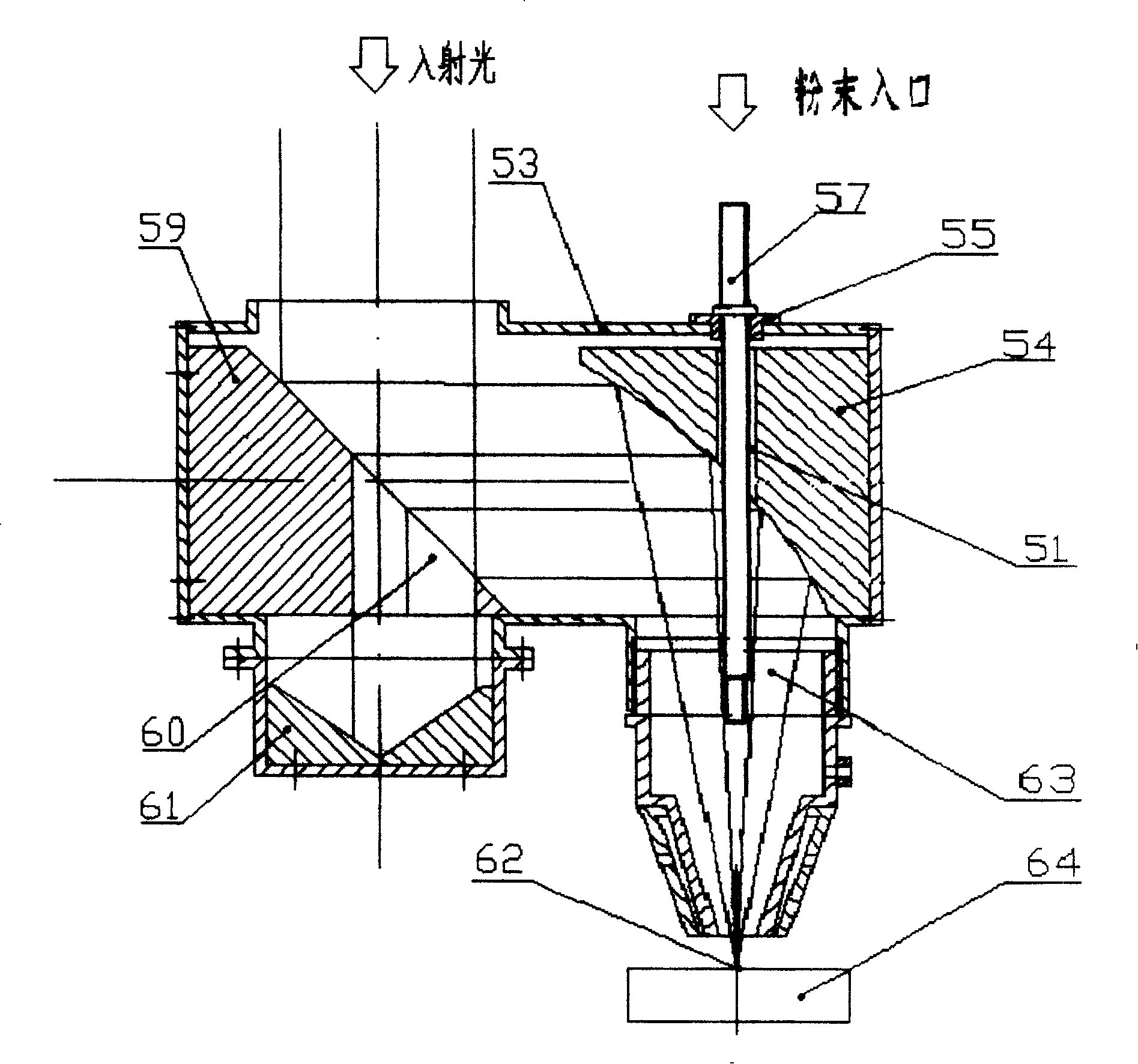
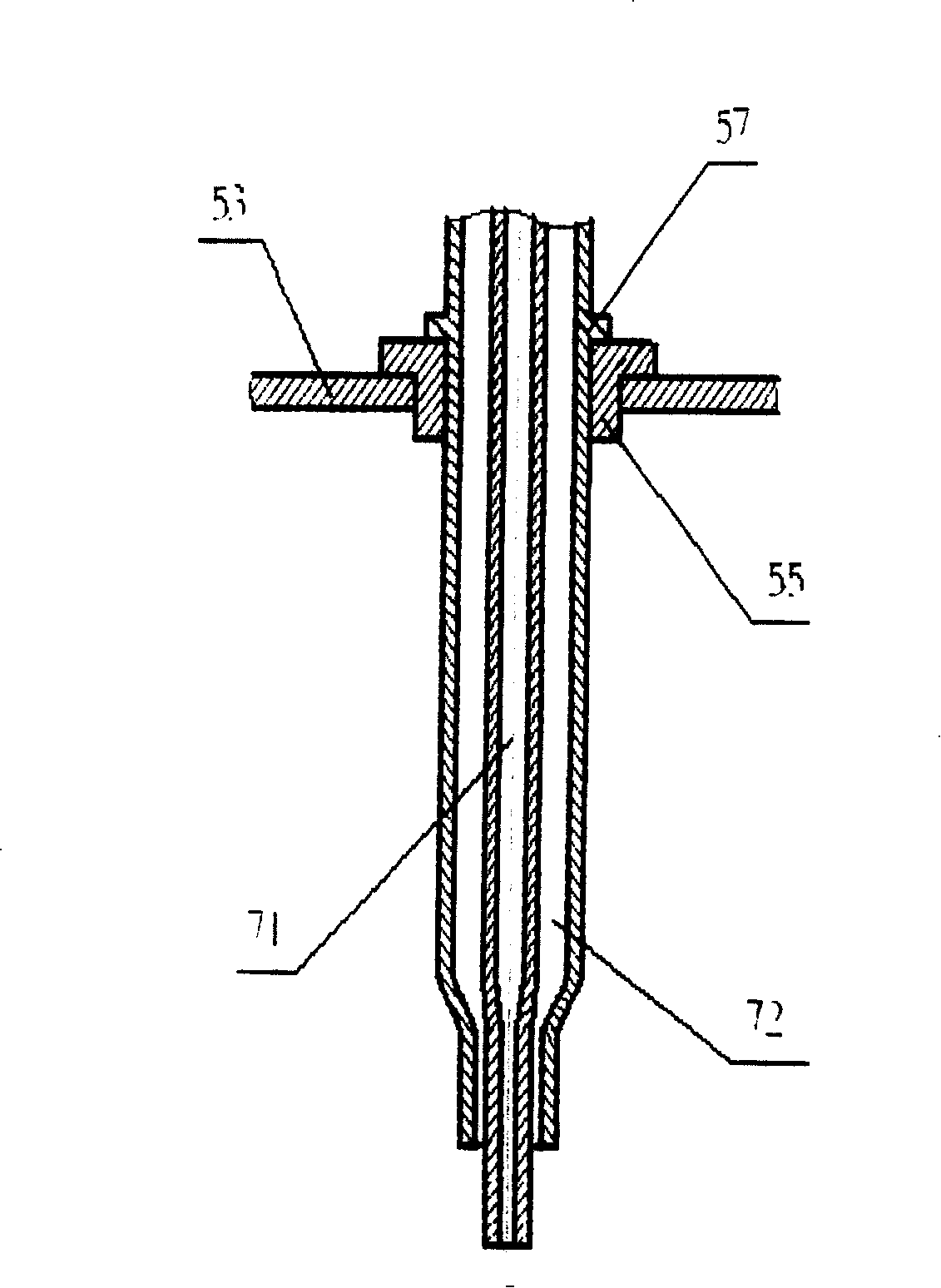
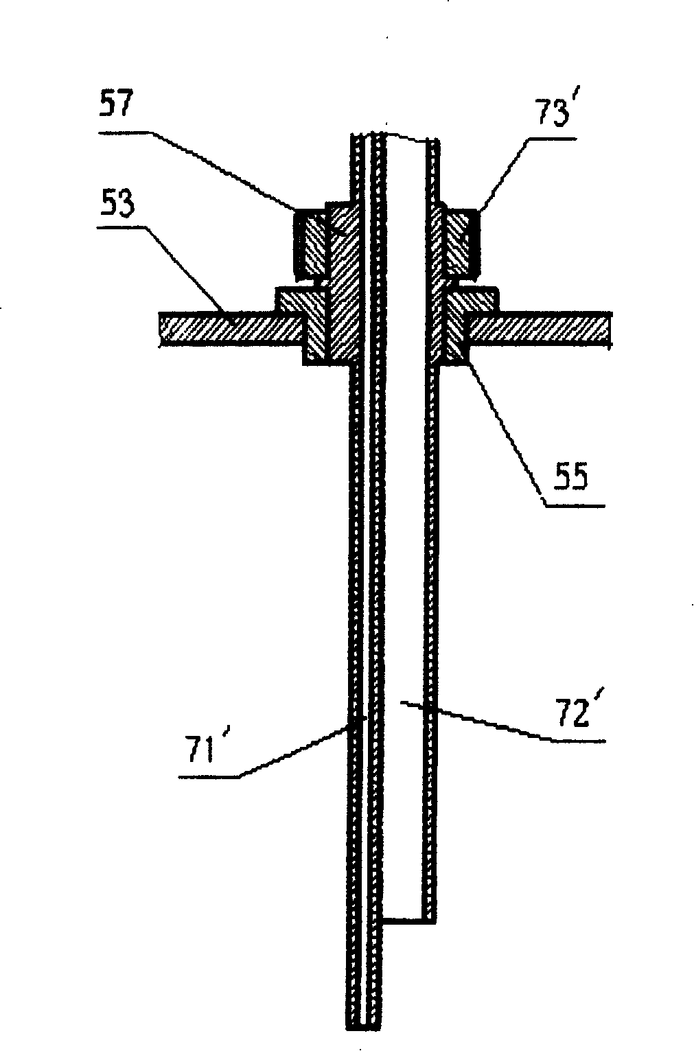
A technology that using laser to melt speckle and mould: using profilometry to layout the scan path of the parts in every layer. Using pipe that has small facula and caliber to deliver powder and melt the outline of the layer, using pipe that has big facula and caliber to deliver powder and melt the inner field of the layer. The beam of single powder and the beam of light have the same axis and perpendicular to the surface of the mould. The diameter of the small facula is 0.5mm to 2mm and the big is 2mm to 10mm, and the diameter of powder spot is slightly big than the facula. The coaxial nozzle that this technology used includes a cylinder, a plane reflector that has placket in the radial, a focusing reflector that has a hole in center, a pipe that use to deliver the powder. The invention can melt in various size of facula. Needn't to adjust multi-channel pipes of powder to pool, The beam of powder and the beam of light can couple the focus of facula and any other space off the focus. The round powder spot of single-channel can scan along any direction and isn't sensitive to direction.
Description
technical field [0001] The invention belongs to the field of laser processing, and in particular relates to a laser spot-variable cladding process and a special coaxial spray head thereof. Background technique [0002] Laser cladding is mainly used for coating cladding, precision three-dimensional rapid manufacturing of parts, etc. During the cladding process, the laser beam is irradiated and focused on the forming surface, and the feeder feeds the metal powder or wire into the focused laser spot on the forming surface. The working process of laser cladding rapid manufacturing is: according to the established three-dimensional solid CAD model, the model is layered along a certain direction with a certain thickness to obtain a series of layer data. After the scanning path planning is performed on the slice data, the motion trajectory of the execution system is generated. The CNC workbench and the coaxial nozzle move according to this trajectory for cladding accumulation pro...
Claims
Login to View More Application Information
Patent Timeline
 Patent Type & Authority Patents(China)
IPC IPC(8): B22F3/105
Inventor 石世宏傅戈雁
Owner SUZHOU UNIV
Features
- R&D
- Intellectual Property
- Life Sciences
- Materials
- Tech Scout
- Unparalleled Data Quality
- Higher Quality Content
- 60% Fewer Hallucinations
Learn More Browse by: Latest US Patents, China's latest patents, Technical Efficacy Thesaurus, Application Domain, Technology Topic, Popular Technical Reports.
© 2025 PatSnap. All rights reserved.Legal|Privacy policy|Modern Slavery Act Transparency Statement|Sitemap|About US| Contact US: help@patsnap.com


