
Vacuum mechanical-arm

A vacuum manipulator and arm technology, applied in the direction of manipulators, program control manipulators, conveyor objects, etc., can solve the bottleneck of vacuum manipulator transmission capacity and other issues, achieve the effect of improving transmission efficiency, optimizing motion path, and achieving compatibility

Active Publication Date: 2008-05-14
BEIJING NAURA MICROELECTRONICS EQUIP CO LTD
View PDF6 Cites 0 Cited by
  • Summary
  • Abstract
  • Description
  • Claims
  • Application Information

AI Technical Summary

Problems solved by technology

[0007] Therefore, the bottleneck of the output rate of most etching equipment at present lies in the transmission capacity of the vacuum manipulator.

Method used


Image

  • Vacuum mechanical-arm
  • Vacuum mechanical-arm
  • Vacuum mechanical-arm

Examples


Embodiment Construction

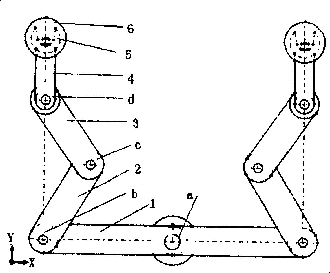
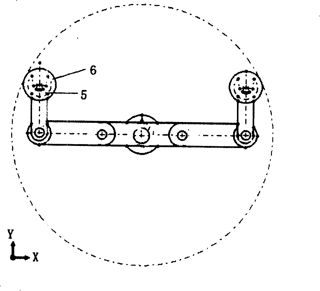
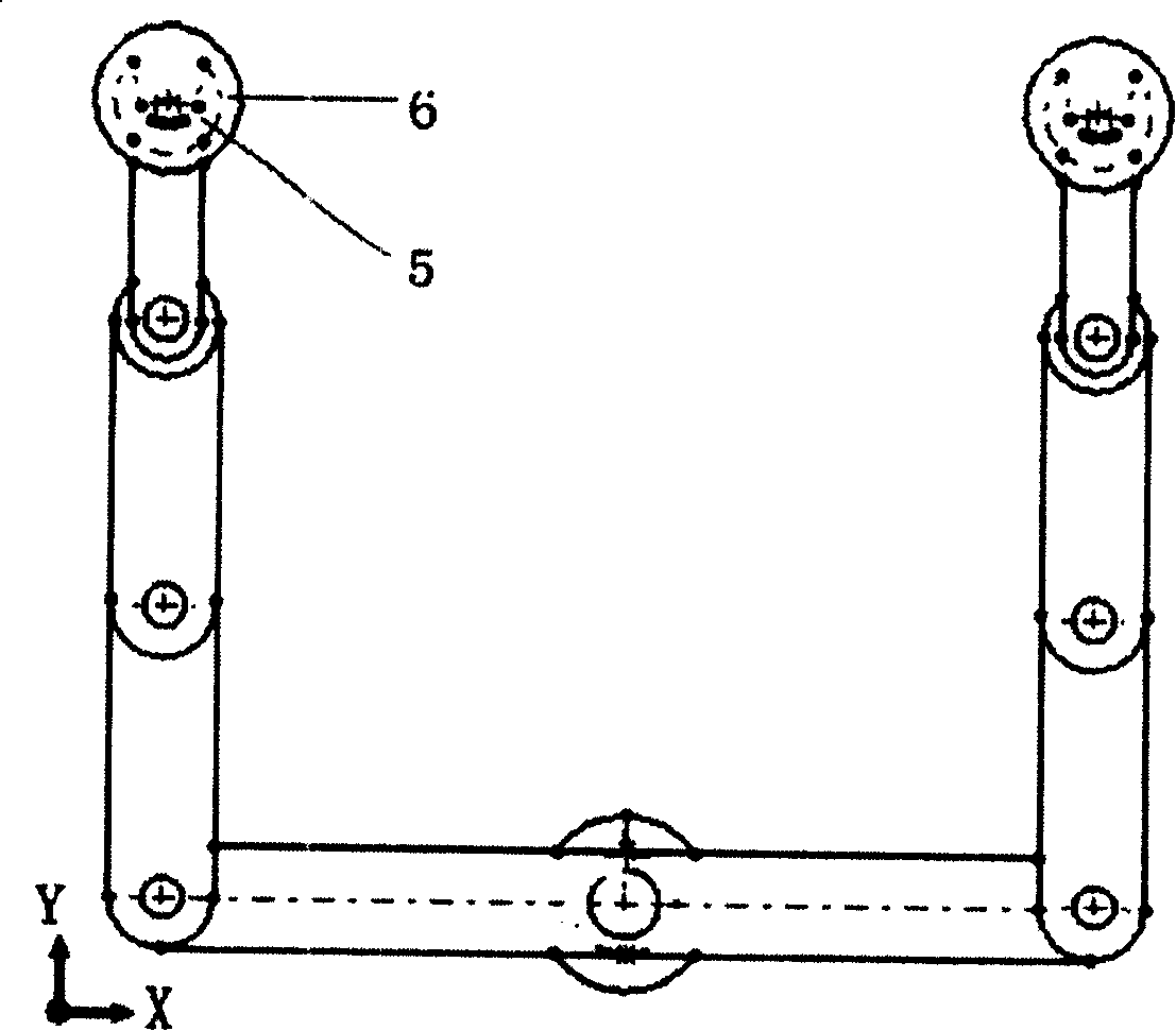
[0027] see figure 1 , the vacuum manipulator of the present invention includes a fixed arm 1 (this arm can also be referred to as the first arm), the fixed arm is fixed on the drive shaft of the motor through a hinge structure, and is located at the center of the vacuum transfer chamber. The two ends of the arm 1 are symmetrically arranged with the second arm 2, the third arm 3 and the fourth arm 4. The arms are connected by a hinge structure, and the free end of the fourth arm 4 is provided with a terminal receiving device for supporting wafers. Actuator 5, the end effector is fixed on the fourth arm 4 through threaded connection, so the compatibility of 200mm wafer and 300mm wafer 6 can be realized by replacing the end effector at the threaded connection according to the process requirements; Software control always makes the center of the end effector 5 move on the line perpendicular to the center of the chamber and the center of the motor drive shaft. Therefore, no matter...


PUM


Abstract

This invention relates to a vacuum manipulator of a vacuum transmission section in the transmission system of a semiconductor etching device including two telescopic arms connected by a fixed hinge joint and each includes a fixed arm, a second arm, a third arm, a fourth arm and a fifth arm connected orderly by a hinged structure, a terminal effector for holding wafers is set at the free end of the fifth arm, the center of which is on the same line with the central shaft of the fourth arm and vertical to the center of the fixed arm and the technical cavity.

Description

technical field [0001] The invention relates to a plasma etching device, in particular to a plasma etching device with an improved quartz cover structure. Background technique [0002] In the transmission system of the etching equipment, the path of the wafer is transferred to the positioning device by the atmospheric robot, and after being positioned by the device, it is transported by the vacuum robot to the etching process chamber for process operation. Usually, in order to save space and facilitate maintenance, the shape of the vacuum transfer chamber is a radial polygonal structure, and the vacuum manipulator is a single-arm or double-arm structure. [0003] When the vacuum manipulator is carrying the wafer, usually the vacuum manipulator first lowers a few millimeters in the vertical direction (generally, the vertical movement distance is within 35mm), and the terminal effector at the front end of the manipulator is extended into the positioning element to support the ...

Claims


Application Information

Patent Timeline
Patent Type & Authority Patents(China)
IPC IPC(8): H01L21/677H01L21/3065B25J9/06
Inventor 董博宇
Owner BEIJING NAURA MICROELECTRONICS EQUIP CO LTD
Learn More