Vacuum cleaner with preseparating structure

A vacuum cleaner and pre-separation technology, applied in vacuum cleaners, suction filters, household appliances, etc., can solve the problems of high dust collection efficiency and low energy consumption, and achieve the effects of small system resistance, load reduction, and overload suppression

Inactive Publication Date: 2008-06-04
王一川
View PDF7 Cites 0 Cited by
  • Summary
  • Abstract
  • Description
  • Claims
  • Application Information

AI Technical Summary

Problems solved by technology

[0003] The technical problem to be solved by the invention is to reduce the complex coefficient of the vacuum cleaner, and also have the advantages of high dust collection efficiency and low energy consumption

Method used


Image

  • Vacuum cleaner with preseparating structure
  • Vacuum cleaner with preseparating structure

Examples


example 1

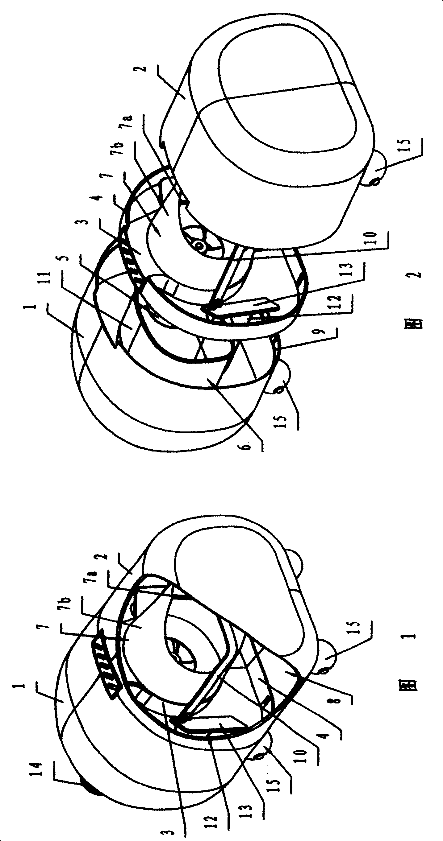
[0016] Referring to Fig. 1 or Fig. 2, this embodiment is a horizontal structure main body.

[0017] Referring to Figure 1 or Figure 2, the body 1 and the card cover 2 that constitute the main body are respectively provided with positioning steps 9, the body 1 and the card cover 2 are respectively fitted from the two ends of the support seat 4, and the support seat 4 is clamped between them . The space in the housing is divided into two laterally by the support base 4 , where the motor 5 is located at one end is the air intake passage 6 , and the filter 7 is located at the end where the dust collection chamber 8 is located. The filter 7 is a bag filter, which is composed of a filter bag 7b and a disc-shaped frame 7a arranged at the bottom of the filter bag 7b. On the U-shaped bracket 10, the U-shaped bracket 10 is fixed on the casing side of the blower fan 3.

[0018] Referring to FIG. 2 , the motor 5 is provided with a crown casing 11 , and the root of the casing 11 is fixed...

example 2

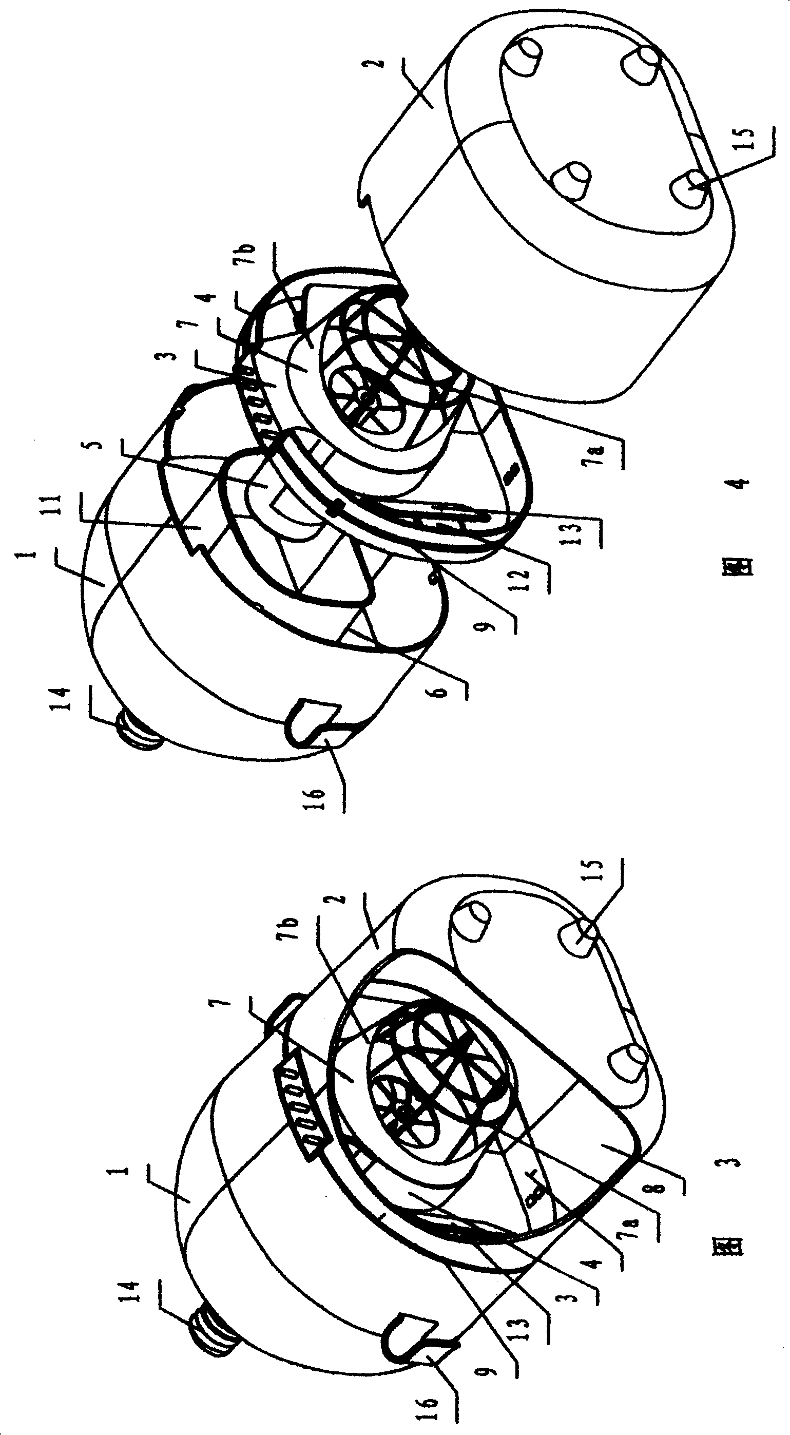
[0023] Referring to Fig. 3 or Fig. 4, this embodiment is a main body of a portable vacuum cleaner that can be used on the back.

[0024] Referring to Fig. 3 or Fig. 4, the fan 3 is installed on a disc-shaped supporting base 4, and the surface of the supporting base 4 is provided with an annular positioning boss 9, and the body 1 and the card cover 2 constituting the main body are respectively fitted from both ends, and the supporting base 4 is sandwiched between the two.

[0025] Referring to Fig. 3 or Fig. 4, the filter 7 is formed by setting a cloth bag 7b on the outer surface of a crown grille cover 7a, and is fixed on the inlet of the blower fan 3 through the crown grille cover 7a.

[0026] Referring to FIG. 3 or FIG. 4 , the two sides of the body 1 and the card cover 2 are provided with straps 16 , and the bottom surface of the card cover 2 is provided with supporting feet 15 .

[0027] The implementation method of this embodiment other than the above is the same as that...


PUM


Abstract

The present invention relates to a vacuum cleaner with preseparation structure. Said vacuum cleaner includes vacuum cleaner main body, and is characterized by that in the interior of shell body of said main body are successively set a motor, a fan and a filter from gas inlet. A disk supporting seat is used for supporting said fan in the interior of said shell body, the internal space of said shell body is divided into two portions in the transverse direction, one end where the meter is mounted is air-intake channel, and one end where the filter is mounted is duct-collecting chamber, the left and right two sides of the described supporting seat are equipped with air inlet respetively, on the air inlet a non-return valve is set respectively.

Description

Technical field: [0001] The present invention relates to a vacuum cleaner, and more particularly to the structural features of the main body of the vacuum cleaner. Background technique: [0002] Existing household vacuum cleaners are all filtering vacuum cleaners, which can be divided into three types according to their shapes: vertical, horizontal, and portable. Its main structure is also composed of three major parts: dust collection chamber, filter, and fan arranged in sequence. Garbage and dust enter the dust collection part with the air, and are filtered by the filter first, then are detained in the dust collection chamber, and the gas is filtered again. After the device, it is discharged through the exhaust port. Since the inlet and outlet of the dust collection chamber are in the same direction, that is, the inlet and outlet of the dust collection chamber are "straight through", even though the volume of the dust collection chamber is large, it cannot achieve separat...

Claims


Application Information

Patent Timeline
Patent Type & Authority Patents(China)
IPC IPC(8): A47L5/00A47L9/10
Inventor 王一川徐锋
Owner 王一川
Why Eureka
Try Eureka