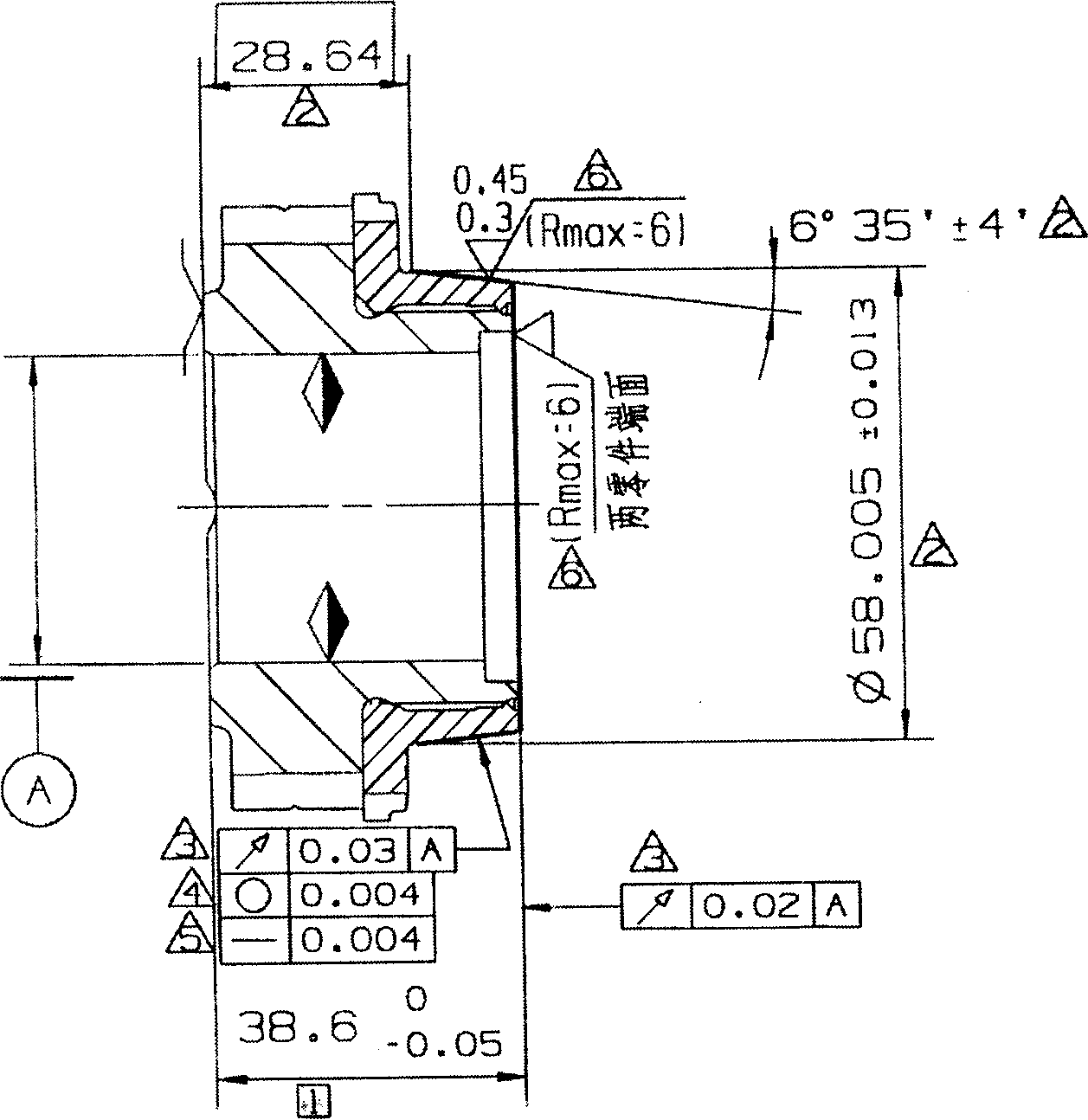
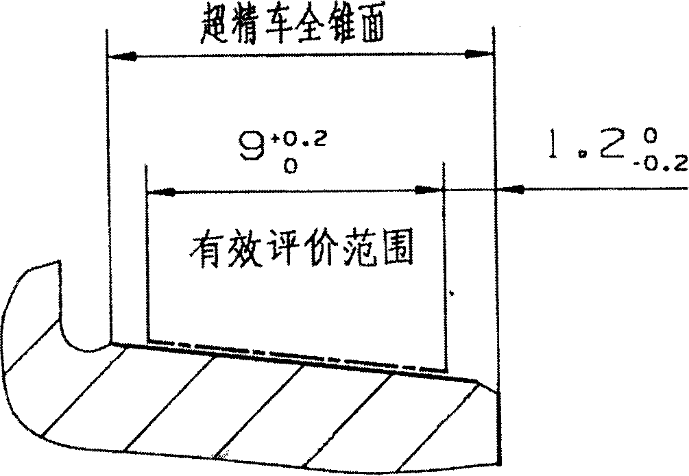
Wet hard turning process of steel part after quenching heat treatment
A cutting method and part technology, applied in the direction of turning equipment, turning equipment, metal processing machinery parts, etc., can solve the problem of improving tool life without improvement, and achieve the effect of prolonging the service life
- Summary
- Abstract
- Description
- Claims
- Application Information
AI Technical Summary
Problems solved by technology
Method used
Image
Examples
Embodiment 1
[0021] The projections of the new and old cutter heads are enlarged, and the phenomenon of "false scrapping" in the process of processing is analyzed by using the principle of thermoplastic flow and combining the measurement data of the surface roughness of the parts.
[0022] Figure 2a , Figure 2b The enlarged projection of the cutter head, the right edge of the cutter head is the rake face. Figure 2a is a projected enlarged view of the new cutter head. From Figure 2b It can be seen that the negative rake angle appears on the rake face, which is formed by the part hitting the rake face of the cutter head during the cutting process, and the new blade does not have it. The angle θ between the original negative chamfer of the new blade head (0.10-0.20mm due to the small cutting depth, which can be regarded as a negative rake angle) and the horizontal line, after cutting 360 parts, the tool wears and the negative chamfer The angle between the edge and the horizontal line ...
Embodiment 2
[0026] The original number of forced tool changes (one-sided cutter head) was 250. When the 250th part was processed, Ra≥0.45μm was measured. The cutter head was enlarged to show that the arc of the cutter tip was worn, and the cutter head was considered scrap .
[0027] The improvement method is to extend the number of forced tool changes, keep all other cutting conditions unchanged, and after crossing the "false scrap" area, the surface roughness of the part is obviously improved. Enlarging the cutter head shows that the arc of the cutter nose is formed again, and the surface roughness of the part formed after crossing the "false scrap" area is often the best, which is also in full agreement with Figure 3. Finally, the number of forced tool changes (one-sided cutter heads) was extended to 470. The Ra value of the surface roughness of the parts is shown in the table below:
[0028]
[0029]
Embodiment 3
[0031]Increase the cutting speed from the original 90m / min to 400m / min. After small batch production, the number of forced tool changes (single-sided cutter heads) can be extended to 500. There is no obvious difference between the measured surface roughness of the part and the surface roughness of the part formed when the original cutting speed is 90m / min.
PUM
| Property | Measurement | Unit |
|---|---|---|
| surface roughness | aaaaa | aaaaa |
| hardness | aaaaa | aaaaa |
| hardness | aaaaa | aaaaa |
Abstract
Description
Claims
Application Information
 - R&D
- Intellectual Property
- Life Sciences
- Materials
- Tech Scout
- Unparalleled Data Quality
- Higher Quality Content
- 60% Fewer Hallucinations
Browse by: Latest US Patents, China's latest patents, Technical Efficacy Thesaurus, Application Domain, Technology Topic, Popular Technical Reports.
© 2025 PatSnap. All rights reserved.Legal|Privacy policy|Modern Slavery Act Transparency Statement|Sitemap|About US| Contact US: help@patsnap.com


