Natural gas liquefying method for gas peak regulation and light hydrocarbon recovery

A light hydrocarbon recovery and natural gas technology, which is applied in the field of natural gas liquefaction, can solve the problems of low cold energy utilization rate, complex process, and lower process liquefaction rate, and achieve the effects of improving utilization efficiency, optimizing heat exchange network, and simple process structure

Inactive Publication Date: 2008-06-04
SOUTH CHINA UNIV OF TECH
View PDF12 Cites 2 Cited by
  • Summary
  • Abstract
  • Description
  • Claims
  • Application Information

AI Technical Summary

Problems solved by technology

[0010] 1. U.S. Patent US6449982, but it needs to use an external cold source to liquefy all the raw material gas, and the operating cost of the process is relatively high
[0011] 2. U.S. patents US6023942 and US6209350, but the process is more complicated, and many compressors are used, which makes the investment and power consumption very large, so it is not suitable for use in the pressure regulating station of the natural gas transmission and distribution pipeline
[0012] 3. U.S. patents US6085546 and US6269656 only use the cooling capacity obtained by expansion to condense the feed gas, but do not separate the LNG produced during the expansion process of the feed gas in the turbo expander, which reduces the liquefaction rate of the process
[0013] 4. U.S. patents US6085547 and US6743829 use throttle valve expansion refrigeration. Since the refrigeration effect of isenthalpy throttling expansion is lower than the isentropic expansion of turbo expander, the cooling capacity obtained is less, which affects the liquefaction rate of the process
[0014] 5. The heat exchange network of the US patent US6378330 is not highly integrated, and the cooling capacity of low-temperature natural gas generated during the production of LNG is not utilized
[0015] 6. In the Chinese patent 200410085540.0 (application number), the pressure of natural gas can be used to do work externally to obtain the cooling capacity required for natural gas liquefaction, but this patent needs to use the method of refrigerant circulation to pre-cool the raw gas, so the energy consumption and operating costs are low. higher
[0016] 7. Chinese patent 02827305.2 (application number) is also a process for producing LNG through expansion refrigeration, but the process is relatively complicated. The LNG produced in the expansion process of the turbo expander is not separated, and only a part of the pre-cooled raw material is used Gas throttling, thereby reducing the natural gas liquefaction rate of the process
[0017] 8. The natural gas liquefaction device researched by the Cryogenic Center of the Chinese Academy of Sciences (Gu Anzhong, On the Development of the LNG Industry, P&cc's CHINALNG——"Petrochemical Construction" LNG Construction Special Issue, 2005) can be used in the pressure regulating station of the natural gas pipeline network. like figure 1 shown, but this process still has the following deficiencies: (1) The heavy hydrocarbons separated from the gas-liquid separator are not depressurized, so the pressure is very high, which is not conducive to storage and transportation; at the same time, the cold energy of heavy hydrocarbons is not fully utilized, Therefore, the utilization rate of cold energy is low
(2) Natural gas expands through the expander to generate low temperature, and part of the natural gas will be liquefied, and the gas-liquid mixture enters the heat exchanger 2 together as a refrigerant, without separating the LNG, which reduces the liquefaction rate of the process

Method used


Image

  • Natural gas liquefying method for gas peak regulation and light hydrocarbon recovery
  • Natural gas liquefying method for gas peak regulation and light hydrocarbon recovery
  • Natural gas liquefying method for gas peak regulation and light hydrocarbon recovery

Examples


Embodiment 1

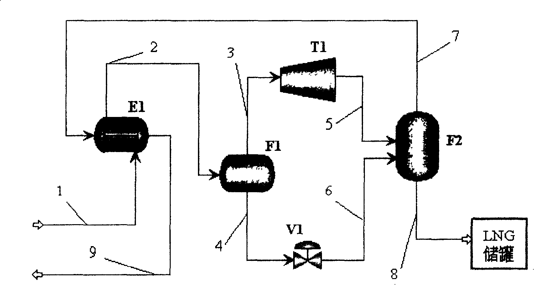
[0045] figure 2 Shows a specific process of the present invention, by figure 2 It can be seen that the specific natural gas liquefaction method is: the pressure is 4.0MPa, the temperature is 25℃, and the flow rate is 68258Nm. 3 / h (about 50t / h) of natural gas (raw gas) is sent to the heat exchanger E1 through the pipeline 1. The source of natural gas is the gasification of imported LNG dry gas, and its composition is as follows:

[0046] Composition content mol%

[0047] Methane 96.60

[0048] Ethane 1.97

[0049] Propane 0.40

[0050] Isobutane 0.07

[0051] N-butane 0.07

[0052] C 5 + Nil

[0053] Nitrogen 0.89

[0054] The raw material gas is pre-cooled in the heat exchanger E1 and is cooled to about -77.0°C. Some natural gas liquid is precipitated to form a gas-liquid mixture, and the gas phase fraction in the fluid is about 98%. Then, the gas-liquid mixture is sent to the gas-liquid separator F1 through the pipeline 2 for separation. Perform isostatic adiabatic separ...

Embodiment 2

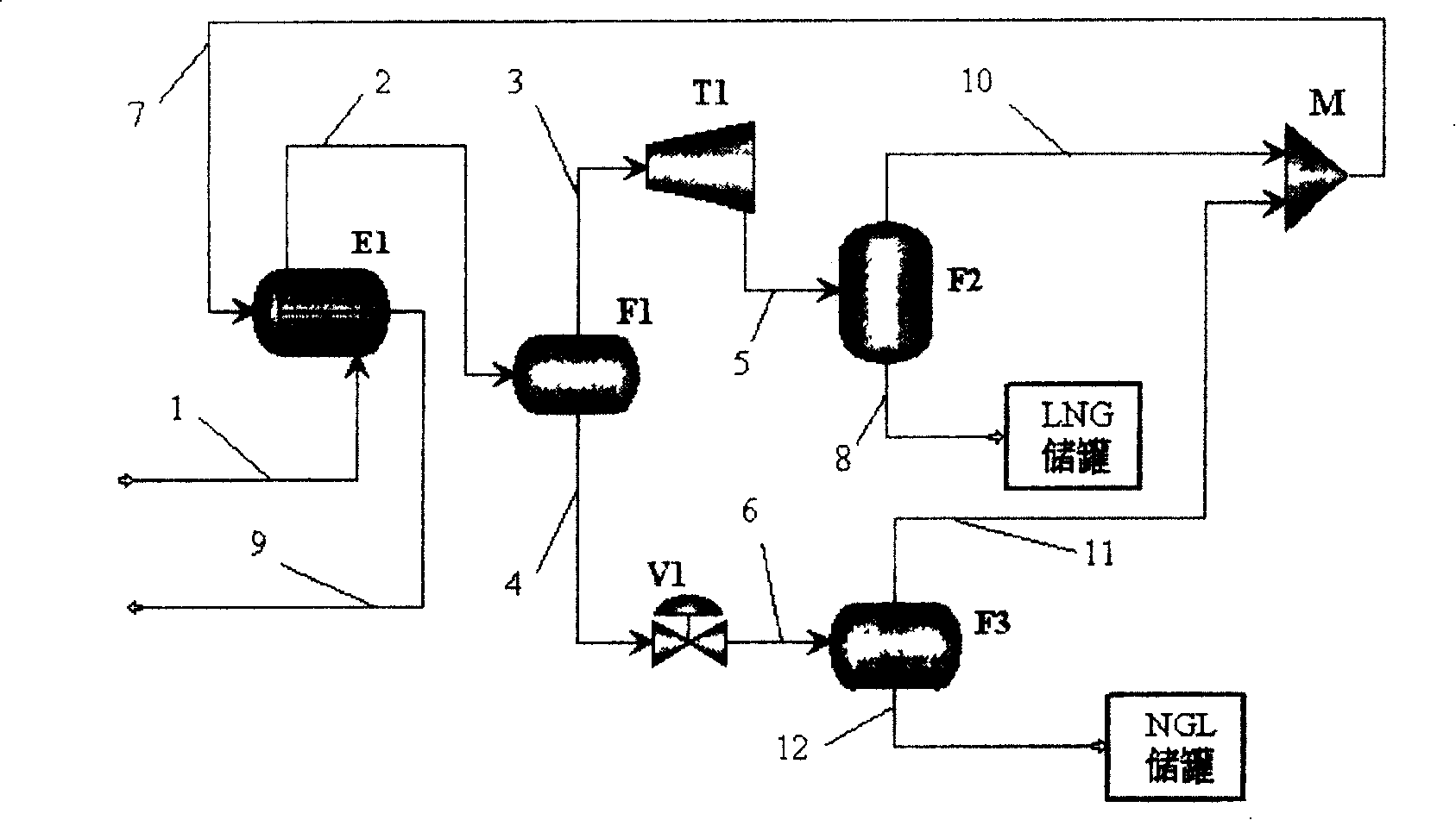
[0071] image 3 Shows another specific process of the present invention, by image 3 It can be seen that the natural gas liquefaction method is specifically as follows: pressure is 2.5MPa, temperature is 25℃, and flow rate is 68258Nm 3 / h (about 50t / h) of natural gas (raw gas) is sent to the heat exchanger E1 through the pipeline 1. The source of natural gas is the gasification of imported LNG dry gas, and its composition is the same as in Example 1.

[0072] The raw material gas is pre-cooled in the heat exchanger E1 and cooled to -92.0°C. Some natural gas liquid is precipitated to form a gas-liquid mixture, and the gas phase fraction in the fluid is 96%. Then, the gas-liquid mixture is sent to the gas-liquid separator F1 through the pipeline 2 for iso-pressure adiabatic separation. The natural gas of 2.5MPa and -92.0°C is separated from the top of the F1 tower and sent to the turboexpander T1 through pipeline 3 for expansion and pressure reduction. The high-pressure natural gas...

Embodiment 3

[0088] Figure 4 Another specific process of the present invention is shown: a certain place uses natural gas from the "West-East Gas Pipeline" and adopts two-stage pressure regulation. In the first stage of pressure regulation, the ultra-high pressure natural gas has been reduced to 1.9MPa, and then sent to the downstream area by pipeline. The downstream secondary pressure regulating station needs to reduce the pressure of the 1.9MPa high-pressure natural gas to 0.3MPa, and then send the natural gas to the user. The composition of "Western Gas" is shown in the following table. Due to the high content of acid gas, it is used in its secondary pressure regulating station. Figure 4 The liquefaction process shown has a processing capacity of 64731Nm 3 / h (about 50t / h).

[0089] Composition content mol%

[0090] Methane 94.10

[0091] Ethane 1.77

[0092] Propane 0.30

[0093] Isobutane 0.06

[0094] N-butane 0.02

[0095] Isopentane 0.02

[0096] N-pentane 0.02

[0097] C 6 0.05...


PUM


Abstract

This invention discloses a liquefying method for natural gas used in gas peak-tuning and light hydrocarbon recovery including the following steps: 1, pre-cooling 2, pre-separation, 3, expansion cooling, in which, the high-pressure natural gas got in step 2 is expanded in a turbine expander to middle pressure sphere to form a gas-liquid mixture by reducing the temperature of the fluid, the high-pressure natural gas liquid got in step 2 is enthalpy-expanded to the mid-pressure sphere via a restrictor to reduce the fluid temperature and form a gas-liquid mixture, 4, separation of gas and liquid: separating the mixture got in step 3 in a separator to obtain liquid and middle-pressure natural gas, in which, the liquid one is input into a storage tank for storing, the middle-pressure gas is taken as the cold source of pre-cooling in step 1 then enters into the middle-pressure natural gas pipe network.

Description

Technical field [0001] The invention relates to the technical field of natural gas liquefaction, in particular to a natural gas liquefaction method for gas peak shaving and light hydrocarbon recovery. Background technique [0002] With the continuous development of China's economy and the adjustment of energy structure, it is an inevitable development trend to use clean energy and vigorously develop the natural gas industry. Before 2020, my country will invest 220 billion yuan in natural gas infrastructure construction: laying 50,000 kilometers of natural gas pipelines; setting up about 10 liquefied natural gas (LNG) stations in the Yangtze River Delta, Bohai Rim and Pan-Pearl River regions, Construct LNG receiving facilities with an import scale of 50 million tons; form a million-ton LNG transportation capacity. As a high-quality clean energy, natural gas also contains a large amount of light hydrocarbon resources, which are very good chemical raw materials. The recovery of ligh...

Claims


Application Information

Patent Timeline
Patent Type & Authority Patents(China)
IPC IPC(8): C10L3/10F25J1/00
CPCF25J1/0022F25J1/0035F25J1/0037F25J1/004F25J1/0201F25J1/0225F25J1/0232F25J3/061F25J3/0635F25J3/064F25J2215/04F25J2220/64F25J2230/08F25J2230/22F25J2230/32F25J2230/60F25J2235/60F25J2240/02F25J2270/91
Inventor 华贲熊永强罗东晓杨艳利
Owner SOUTH CHINA UNIV OF TECH
Why Eureka
Try Eureka