
Modified wire adapting piece

A technology for wire connection and electrical conductivity, which is applied to the needle tip/slotted plate contact used to penetrate the insulated wire/cable core wire, etc., which can solve the problems of high production process requirements, easy falling off of insulating tape, and high operation accuracy. , to achieve the effect of strong operability, simple production and simplified connection steps

Inactive Publication Date: 2008-06-18
齐俊曌
View PDF5 Cites 0 Cited by
  • Summary
  • Abstract
  • Description
  • Claims
  • Application Information

AI Technical Summary

Problems solved by technology

This method is not only complicated in operation steps, but also takes a long time, and it is not suitable for live operation, which affects work efficiency.
In addition, after long-term use, the insulating tape wrapped on the outside is easy to fall off, and the insulating sleeve is also easy to slip off, making the connection of the wires exposed, which poses a great potential safety hazard for electricity use
[0003] In 2005, the applicant applied for an invention patent named electric wire splicing connector, the application number is 200510054986.1. Its structure is mainly composed of a metal ring sleeve and an insulating sleeve. This kind of structure requires high manufacturing technology and is difficult to manufacture. The teeth are formed by folding the edge of the metal plate inwards. The actual operation requires high precision, and the practical effect is not obvious.

Method used


Image

  • Modified wire adapting piece
  • Modified wire adapting piece
  • Modified wire adapting piece

Examples


Embodiment Construction

[0010] Embodiments of the present invention will be described in detail below in conjunction with the accompanying drawings.

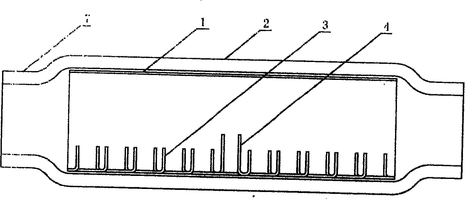
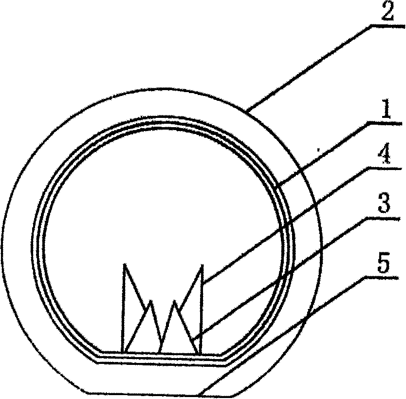
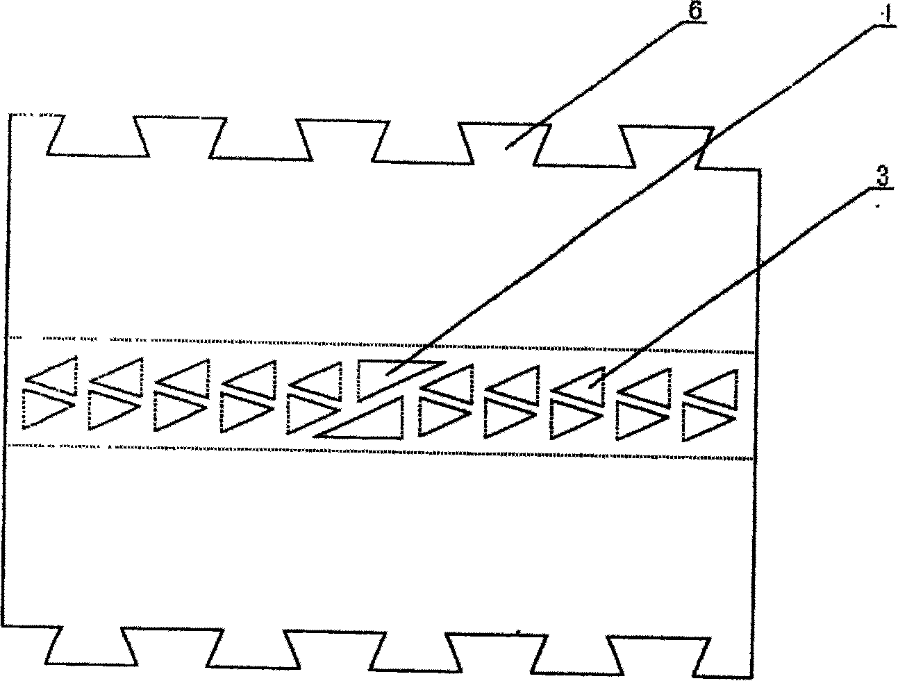
[0011] The invention is an improved wire connector, which includes a metal sleeve 1 and an insulating sleeve 2 . Such as image 3 As shown, the metal sleeve 1 is made by bending a square metal plate with good electrical conductivity. A plurality of triangular metal plate blocks are folded horizontally in the middle of the inner side of the metal plate, and after being folded, they are perpendicular to the inner surface of the metal sleeve 1. The crimping tooth 3 is formed, and the tooth end of the crimping tooth 3 is pointed, which is beneficial to penetrate the insulating layer of the wire. The above-mentioned multiple crimping teeth 3 form a crimping tooth row, which is generally designed as two rows, and the crimping teeth 3 in each row are arranged in reverse. In the middle of each row of crimping teeth 3, there is a positioning tooth 4 that is h...


PUM


Abstract

The invention relates to a wire connector, which is formed by metal muffle and insulated muffle, wherein the metal muffle is inside the insulated muffle; and the invention is characterized in that: the inner side of metal muffle that transversely protruded forms the compression tooth; the compression tooth is vertical to the inner side surface of metal muffle, that longitudinally arranged to form compression tooth row; when using, the invention can avoid removing wire insulated layer, to quickly complete connection, and avoid shortening the wire length. And the connecting point is firm and stable, with high efficiency.

Description

technical field [0001] The invention belongs to the field of electric engineering, in particular to an improved special connector for wire splicing. Background technique [0002] Wires are used in all walks of life, such as wires used to transmit electricity, signal lines used to transmit information, etc. In actual operation, it is often necessary to connect wires. At present, for the connection of wires, the typical operation procedure is: first remove the insulation layer on the outside of the wire, expose the inner core, then twist or weld the ends of the two inner cores together, and finally wrap insulating tape or install insulating sleeve . This method is not only complicated in operation steps, but also takes a long time, and it is not suitable for live operation, which affects work efficiency. In addition, after long-term use, the insulating tape wrapped on the outside is easy to fall off, and the insulating sleeve is also easy to slip off, so that the connection ...

Claims


Application Information

Patent Timeline
Patent Type & Authority Patents(China)
IPC IPC(8): H01R4/24
Inventor 齐俊曌
Owner 齐俊曌
Learn More