Poppet valve having an improved valve seat

A valve seat and valve cavity technology, applied in the field of pneumatic valve components, can solve the problems of unable to accommodate the stroke length, shorten the service life of valve components, and damage parts, so as to keep the system process stable and reliable, prevent valve stroke lengthening, timing and The effect of maintaining precision

Inactive Publication Date: 2008-06-25
MAC VALVES INC
View PDF8 Cites 1 Cited by
  • Summary
  • Abstract
  • Description
  • Claims
  • Application Information

AI Technical Summary

Problems solved by technology

However, as the valve stroke length increases due to seat degradation as described above, the clearance in the actuator assembly cannot accommodate the longer stroke length and the armature will start hitting the valve body or pole piece
This results in a "hammer-anvil" effect between the various components, causing damage to these components and hammered particles can sometimes fall into the valve body and air flow path
These conditions cause the valve to wear out quickly, further shortening the life of the valve assembly
When valve assemblies are used in high speed and highly repetitive manufacturing and process environments, the shortened life of valve assemblies results in frequent replacement of these valve assemblies

Method used


Image

  • Poppet valve having an improved valve seat
  • Poppet valve having an improved valve seat
  • Poppet valve having an improved valve seat

Examples


Embodiment Construction

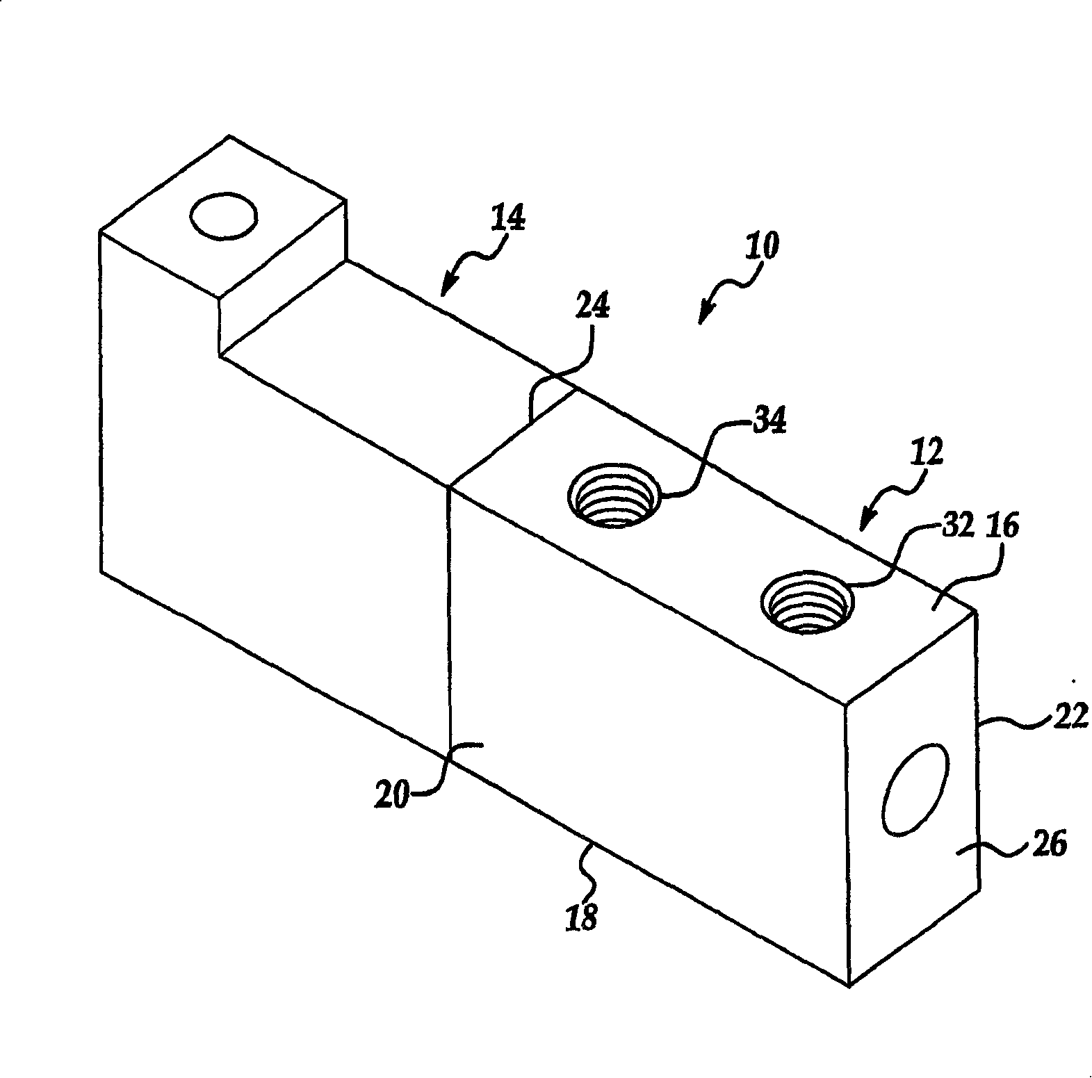
[0023] Referring to the drawings, wherein like reference numerals are used throughout to designate like structures, the pneumatic valve assembly of the present invention is indicated generally at 10 . Such as figure 1 As shown, the pneumatic valve assembly includes a valve body 12 and an electromagnetic actuator assembly, such as a solenoid 14 , mounted on the valve body 12 . The valve body 12 has a thin rectangular shape formed with a top surface 16 and a bottom surface 18 , a pair of opposing sides 20 , 22 extending between the top surface 16 and the bottom surface 18 , and end surfaces 24 , 26 . The actuator assembly 14 is mounted on the end face 24 of the valve body 12 . The actuator of the present invention may be of any known type typically used in pneumatic valves, such as an electromagnetic solenoid with a floating armature and a lost motion bias function, such as in prior art U.S. Patent No. 4,438,418 or No. .3538954, both of which are incorporated herein by referen...


PUM


Abstract

A pneumatic valve assembly (10,110) including a valve body (12,112) having an inlet port (30,130) in fluid communication with a source of pressurized air and a valve bore (36,136) extending axially within the valve body (12,112) with a valve member (46,146) movable between predetermined positions within the valve bore (36,136). The valve member (46,146) selectively movable to direct a flow of pressurized air from the inlet port (30,130) through the valve bore (36,136) to an outlet port (32,132). A valve element (52,152) is disposed upon the valve member (46,146) having an angular valve sealing surface (62,162), and a valve seat (82,182) is defined in the valve bore (36,136) formed at an oblique angle to provide a sealing contact with the valve sealing surface (62,162) when the valve member (46,146) is in a closed position thereby interrupting said flow of pressurized air.

Description

technical field [0001] The present invention relates generally to pneumatic valve assemblies, and more particularly to poppet valves having improved valve seats. Background technique [0002] Pneumatic valve assemblies are well known in the art of controlling the flow of compressed air into and out of various pneumatically actuated devices such as linear actuators, rotary actuators, air outlets or any other pneumatic device requiring precise control of working air or application. In the prior art, a type of pneumatic valve currently used in many situations is usually a poppet valve. Poppet valves are particularly useful with, for example, pilot operated pneumatic valves as part of an overall fluid power system. A conventional poppet valve arrangement includes a valve member movably supported within a valve body between predetermined positions. These positions are generally defined by the arrangement of the valve seat in the valve cavity. The valve member has a valve elem...

Claims


Application Information

Patent Timeline
Patent Type & Authority Patents(China)
IPC IPC(8): F15B13/044F16K1/38F16K11/04F15B13/04F16K11/044F16K11/048
CPCF16K11/048F16K11/044F15B13/0405Y10T137/86895Y10T137/86622Y10T137/86686F15B13/044F16K1/38
Inventor K·C·威廉斯
Owner MAC VALVES INC
Why Eureka
Try Eureka