Unlock instant, AI-driven research and patent intelligence for your innovation.

Line coding scheme for digital communications, transmission method and apparatus

A digital communication and transmission device technology, applied in the field of optical communication systems, can solve problems such as intersymbol interference, limitation of data transmission speed and distance, and widening of input pulses

Inactive Publication Date: 2008-07-02
TELEFON AB LM ERICSSON (PUBL)
View PDF2 Cites 0 Cited by
  • Summary
  • Abstract
  • Description
  • Claims
  • Application Information

AI Technical Summary

Problems solved by technology

However, optical fibers in use today have properties that limit the speed and distance of data transmission
[0003] Dispersive fiber broadens the input pulse, causes intersymbol interference at the receiver, and limits the maximum connection distance for prespecified data rates

Method used


Image

  • Line coding scheme for digital communications, transmission method and apparatus
  • Line coding scheme for digital communications, transmission method and apparatus
  • Line coding scheme for digital communications, transmission method and apparatus

Examples


Embodiment Construction

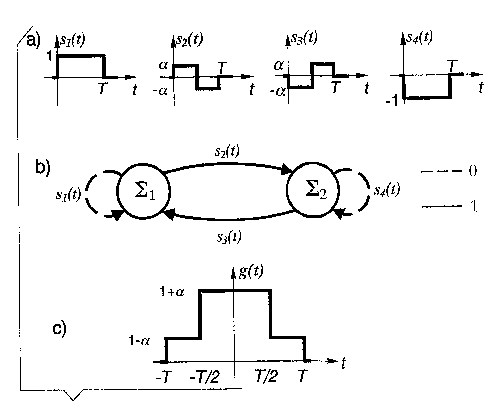
[0042] Referring to these drawings, figure 1 The state diagram and basic signal set associated with the first embodiment of the invention are shown in the first order case.

[0043] As shown, the new line coding uses 4 waveforms or basic signals s i (t), if figure 1 (a). It will be noted that the fundamental signal constitutes two pairs, one of which (e.g. s1 (t) and s 2 (t)) is another pair (i.e. s respectively 4 (t) and s 3 (t)) is negative. In addition, two of the fundamental signals (s 2 (t) and s 3 (t)), i.e. one signal forms a pair, scaled with a factor α. The factor α is chosen to produce the best spectral shape. The state diagram related to the first line coding of the present invention has two states, such as figure 1 (b). The coding state is denoted as ∑ 1 and ∑ 2 while the fundamental signal is denoted as s i (t), i=1, 2, 3, 4.

[0044] figure 2 A transmitter arrangement according to the invention is represented, wherein the source of information SO...


PUM


Abstract

A coding scheme of order n for digital communications, in particular optical communication, for obtaining a coded signal x(t) which represents binary data which are constituted by sequences of information bits {u} with rate T, the scheme having N=2 states, named SIGMA i, i=1,2,...,N, and comprising predetermined elementary signals si(t) which are combined in the signal x(t). According to the scheme, if at the time t=kT the coding is in a state SIGMA m of the N states, the arrival of the information bit uk of the sequence {u} forces a transition to the state SIGMA q of the N states and the selection of the elementary signal si(t) as x(t), where q and i are given by the following equations: d1=m-1 mod 2; d0=d1+uk mod 2; r=2(m-1)+d0; q=(r mod N)+1; and (formula).

Description

technical field [0001] The present invention relates to the field of encoding data for continuous transmission in a transmission device, and is particularly applicable, but not limited to, the field of optical communication systems. Background technique [0002] Optical communication systems are an important and rapidly growing component of communication networks. The expression "optical communication system" as used herein refers to any system that uses optical signals to communicate information. Such optical systems include, but are not limited to, telecommunications systems, cable television systems, and local area networks (LANs). Optical communication systems are configured to carry information in modulated light beams carried on optical fibers. However, the optical fibers used today have characteristics that limit the speed and distance of data transfer. [0003] Dispersive fiber broadens the input pulse, causes intersymbol interference at the receiver, and limits t...

Claims


Application Information

Patent Timeline
Patent Type & Authority Patents(China)
IPC IPC(8): H03M5/20H04B10/61H04B10/2513H04B10/516H04L25/48H04L25/49H04L25/497
CPCH04L25/497
Inventor E·福雷斯蒂里G·普拉蒂
Owner TELEFON AB LM ERICSSON (PUBL)
Features
  • R&D
  • Intellectual Property
  • Life Sciences
  • Materials
  • Tech Scout
  • Unparalleled Data Quality
  • Higher Quality Content
  • 60% Fewer Hallucinations
Learn More