
Cam-retractable paddy field driving wheel

A drive wheel, telescopic technology, applied in the direction of the wheel with shovel-shaped grip teeth, etc., can solve the problems of increased power consumption, increased dead weight of the drive wheel, and low work efficiency, so as to reduce the total power consumption and increase the driving speed Resistance, work efficiency improvement effect

Inactive Publication Date: 2008-07-16
阳尧端
View PDF10 Cites 0 Cited by
  • Summary
  • Abstract
  • Description
  • Claims
  • Application Information

AI Technical Summary

Problems solved by technology

[0002] At present, there are two kinds of walking driving devices commonly used in agricultural machinery products at home and abroad, which are divided into crawler type and wheel type. The crawler type device is suitable for use in northern dry fields, but due to high cost, heavy weight, fast wear, high power consumption, and low work efficiency, It has the defect of mud and grass, and the field surface is compacted, so it is not suitable for walking in muddy fields in southern mountainous and hilly areas
Although the wheeled device is light in weight and simple in structure, because its outer diameter and the protruding part of the driving blade remain unchanged, the defects of sticky mud and grass are common when this kind of wheel is walking in the muddy paddy field, and the working time is slightly longer. Long, the gap between the two protruding parts of the outer edge of the wheel is completely covered with mud and grass, and the mud grass rolls with the wheel, which increases the weight of the driving wheel and increases power consumption, causing the engine to stall in the muddy paddy field.
In addition, because the gap is filled with mud and grass with high viscosity, the extension of each driving blade is reduced, and the driving force is lost, resulting in slipping in place, gradually sinking, and unable to work normally.
In short, the above-mentioned driving devices generally have the disadvantages of mud and grass, easy to block, high power consumption, low efficiency, and poor driving performance in muddy paddy fields.

Method used


Image

  • Cam-retractable paddy field driving wheel
  • Cam-retractable paddy field driving wheel
  • Cam-retractable paddy field driving wheel

Examples


Embodiment Construction

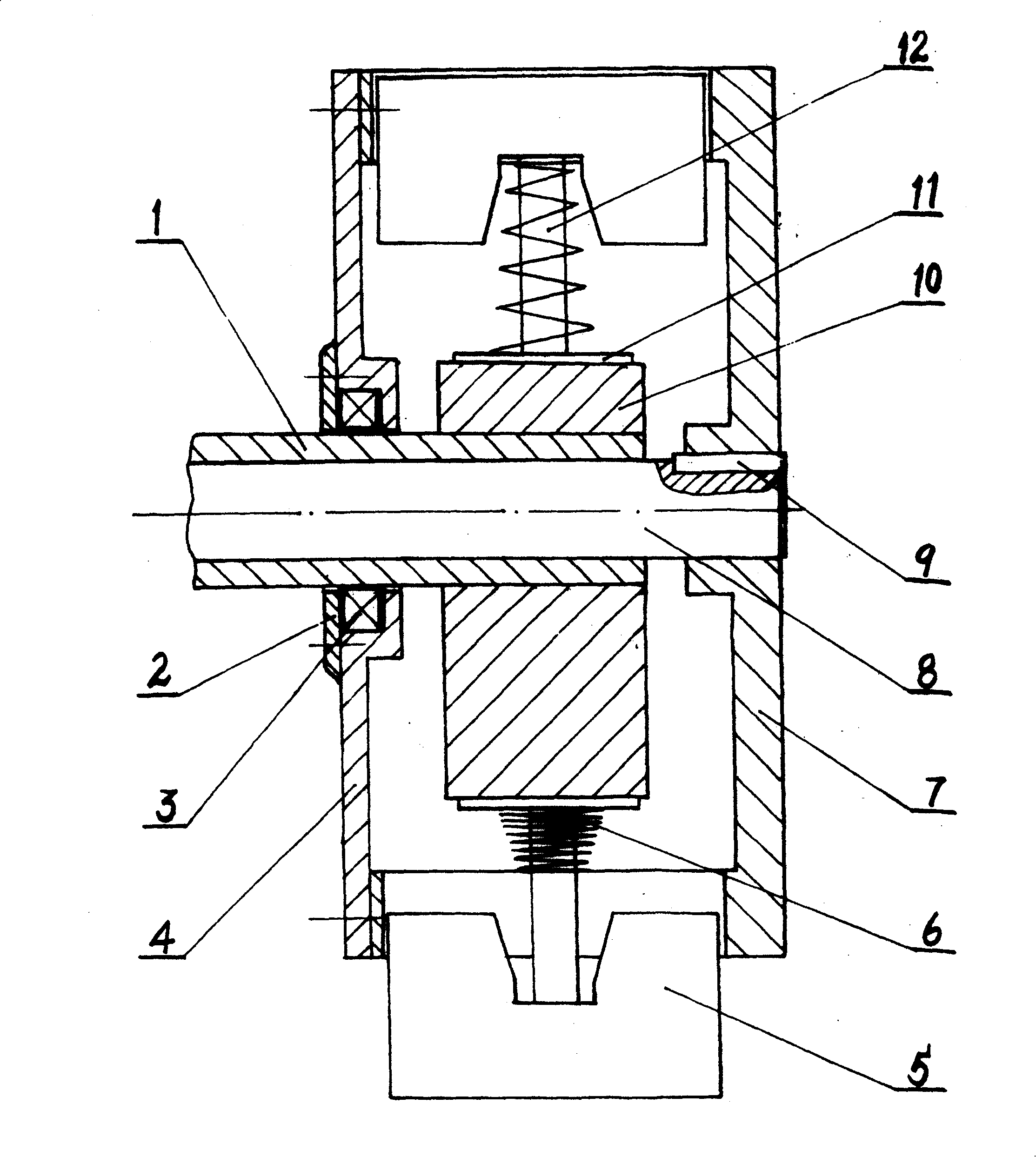
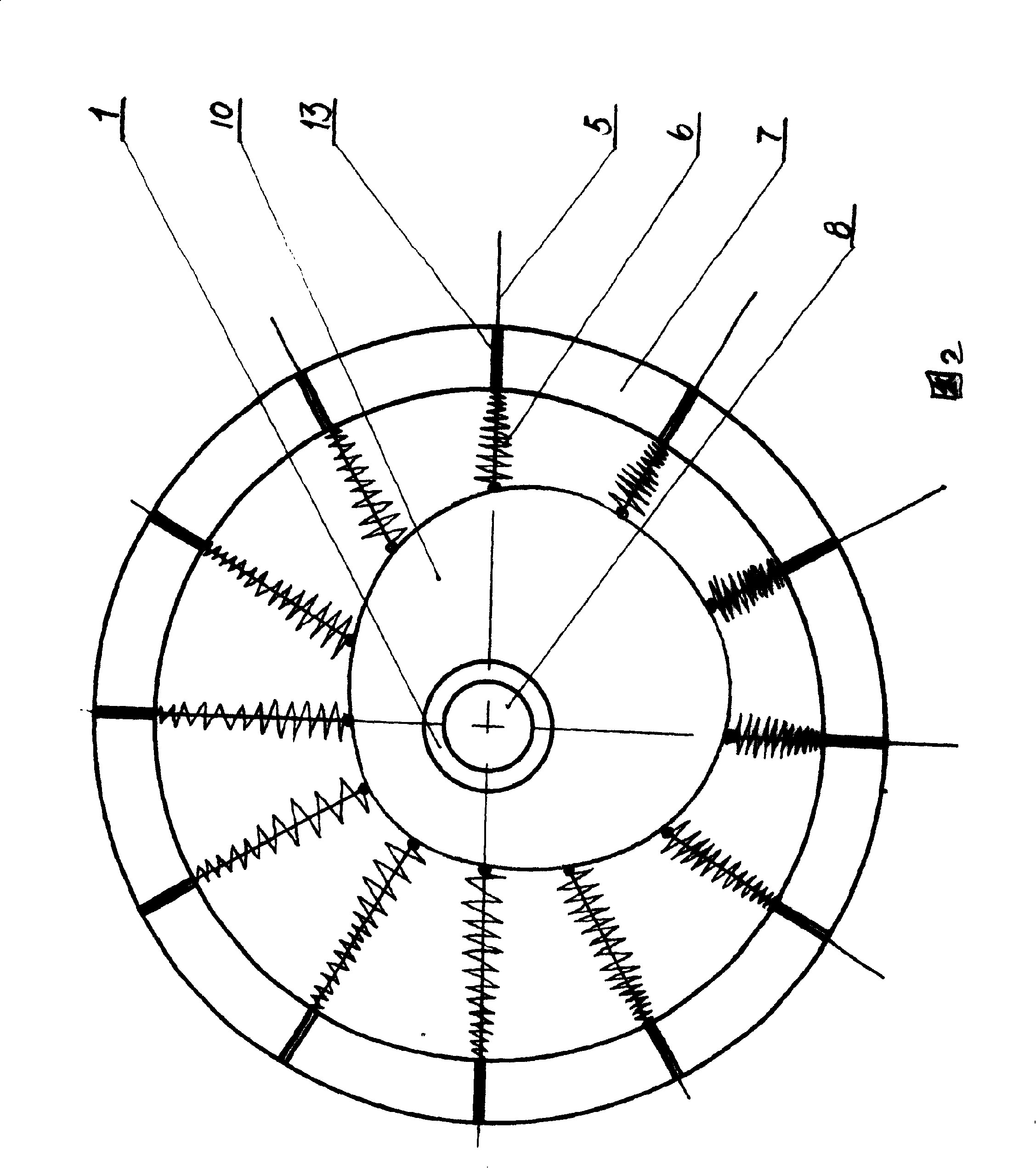
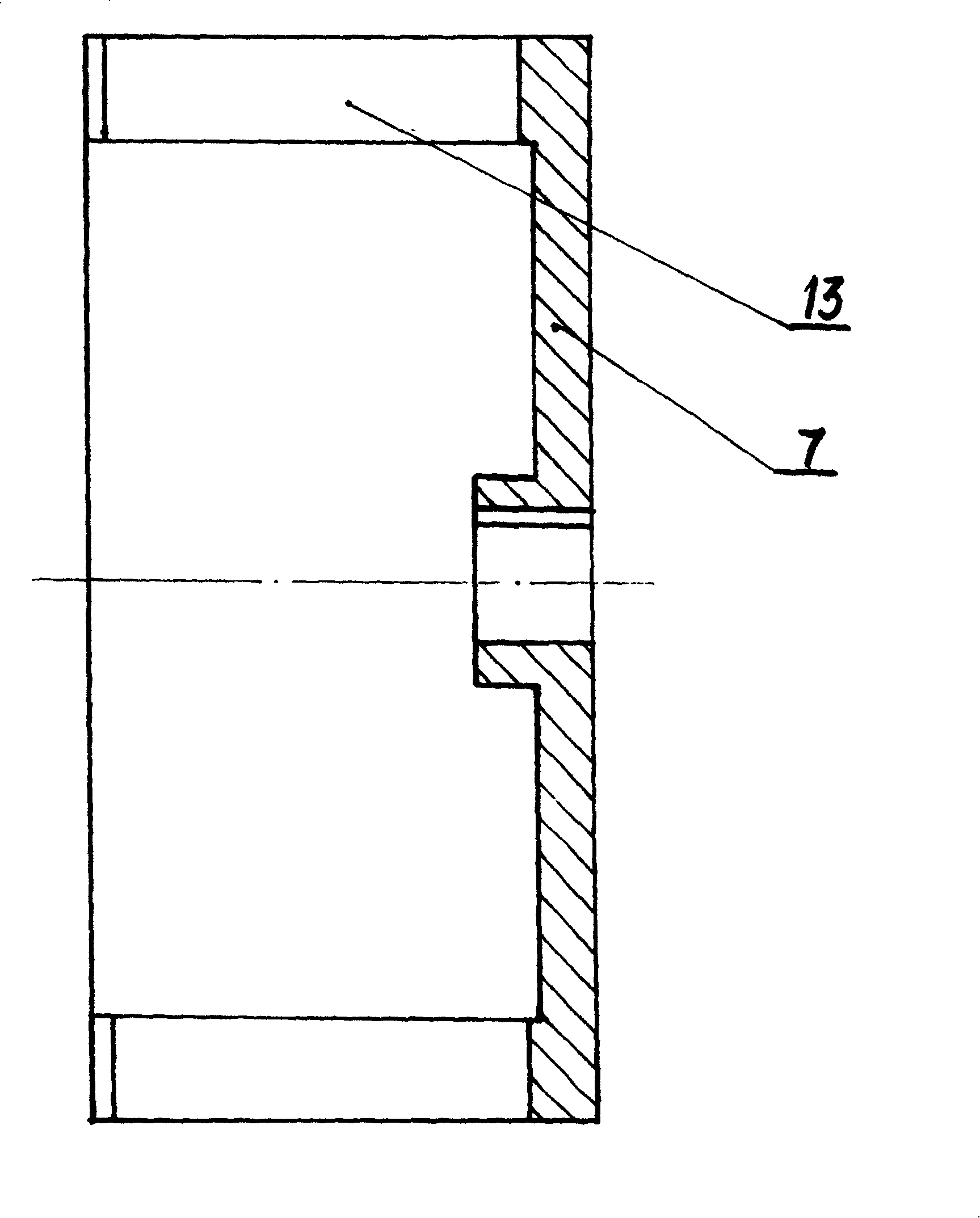
[0023] As shown in the figure, the present invention includes a main drive wheel 7 and a drive shaft 8, both of which are connected with a flat key 9. There is a telescopic opening 13 on the main drive wheel 7, and the telescopic blade 5 expands and contracts in the telescopic opening 13 under the action of the elastic force. The generation of the elastic force and the telescopic movement depend on the shape of the conical compression spring 6, the cam 10 and the rotation of the main driving wheel 7. The other links are formed in cooperation with each other. The contact pressure plate 11 forms a whole with the blade connecting shaft 12 and the telescopic blade 5. The conical compression spring 6 is mounted on the blade connecting shaft 12. The small-diameter end of the conical compression spring 6 contacts the inner circle surface of the main driving wheel 7, and the large-diameter end exerts pressure on the contact platen 11 so that it remains in contact with the cam 10 all t...


PUM


Abstract

This invention relates to a paddy field driving wheel with an expansion cam, in which, a round main driving wheel has an expansion port with expansion vanes, which constitute an expansion body with a vane connection shaft, a contacted pressure board and a compressing spring, the contacted pressure plate always contacts with the cam profile, the cam is fixed on the machine by a fixing shaft, the bearing cover and a sealing cover are movably connected with the fixed shaft by the bearing, the main driving wheel is connected with driving shaft key and the driving shaft is connected with the shift system of the host characterizing in good driving ability in mud paddy fields, small power cost and big driving force and high working efficiency.

Description

technical field [0001] The invention relates to an agricultural machine used as a driving wheel. The cam telescopic paddy field driving wheel has a wide application range and is particularly suitable for being used as a muddy paddy field driving wheel on the agricultural machine. Background technique [0002] At present, there are two kinds of walking driving devices commonly used in agricultural machinery products at home and abroad, which are divided into crawler type and wheel type. The crawler type device is suitable for use in northern dry fields, but due to high cost, heavy weight, fast wear, high power consumption, and low work efficiency, It has the defect of mud and grass, and the field surface is compacted, so it is not suitable for walking in muddy fields in southern mountainous and hilly areas. Although the wheeled device is light in weight and simple in structure, because its outer diameter and the protruding part of the driving blade remain unchanged, the defec...

Claims


Application Information

Patent Timeline
Patent Type & Authority Patents(China)
IPC IPC(8): B60B15/12
Inventor 阳尧端
Owner 阳尧端
Learn More