Eureka AIR delivers breakthrough ideas for toughest innovation challenges, trusted by R&D personnel around the world.

Piston compressor

A piston type and compressor technology, which is applied in compressors, piston pumps, liquid displacement machines, etc., and can solve problems such as jamming, leakage, and wear

Inactive Publication Date: 2008-07-16
LEYBOLD VAKUUM GMBH
View PDF5 Cites 0 Cited by
  • Summary
  • Abstract
  • Description
  • Claims
  • Application Information

AI Technical Summary

Problems solved by technology

Mechanical check valves exhibit mechanical inertia, can stick or leak, and are subject to wear

Method used


Image

  • Piston compressor
  • Piston compressor
  • Piston compressor

Examples


Embodiment Construction

[0027] Several embodiments of the present invention are described in detail below with reference to the accompanying drawings.

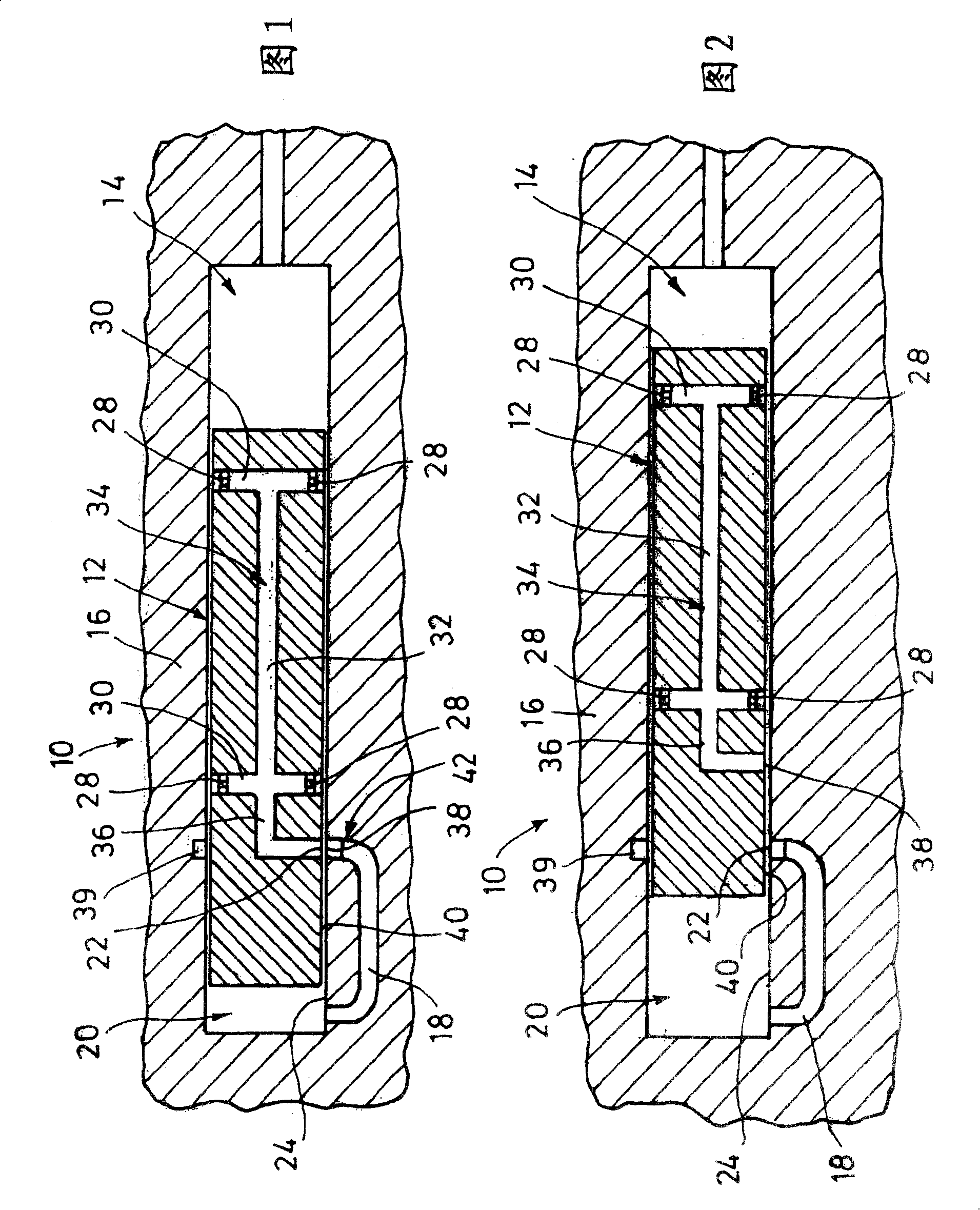
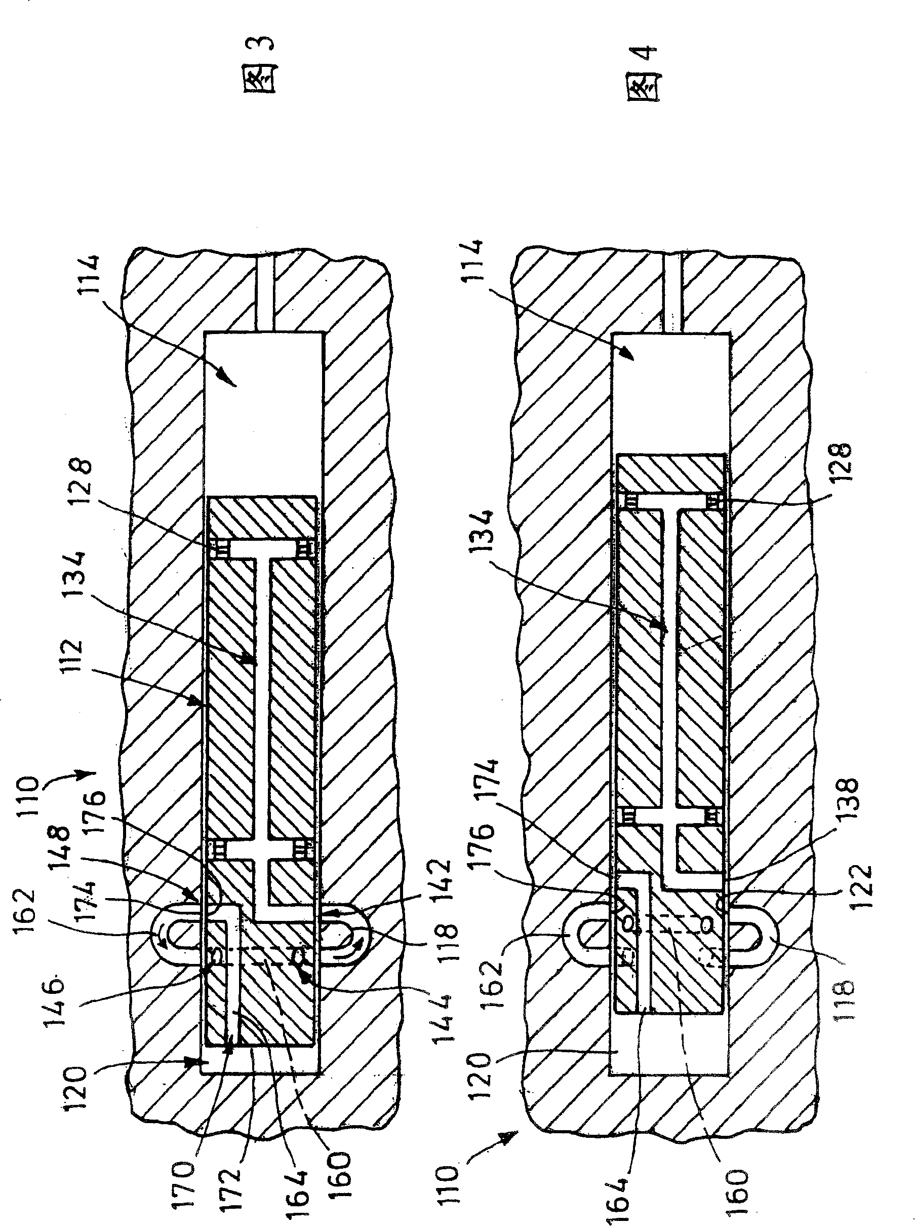
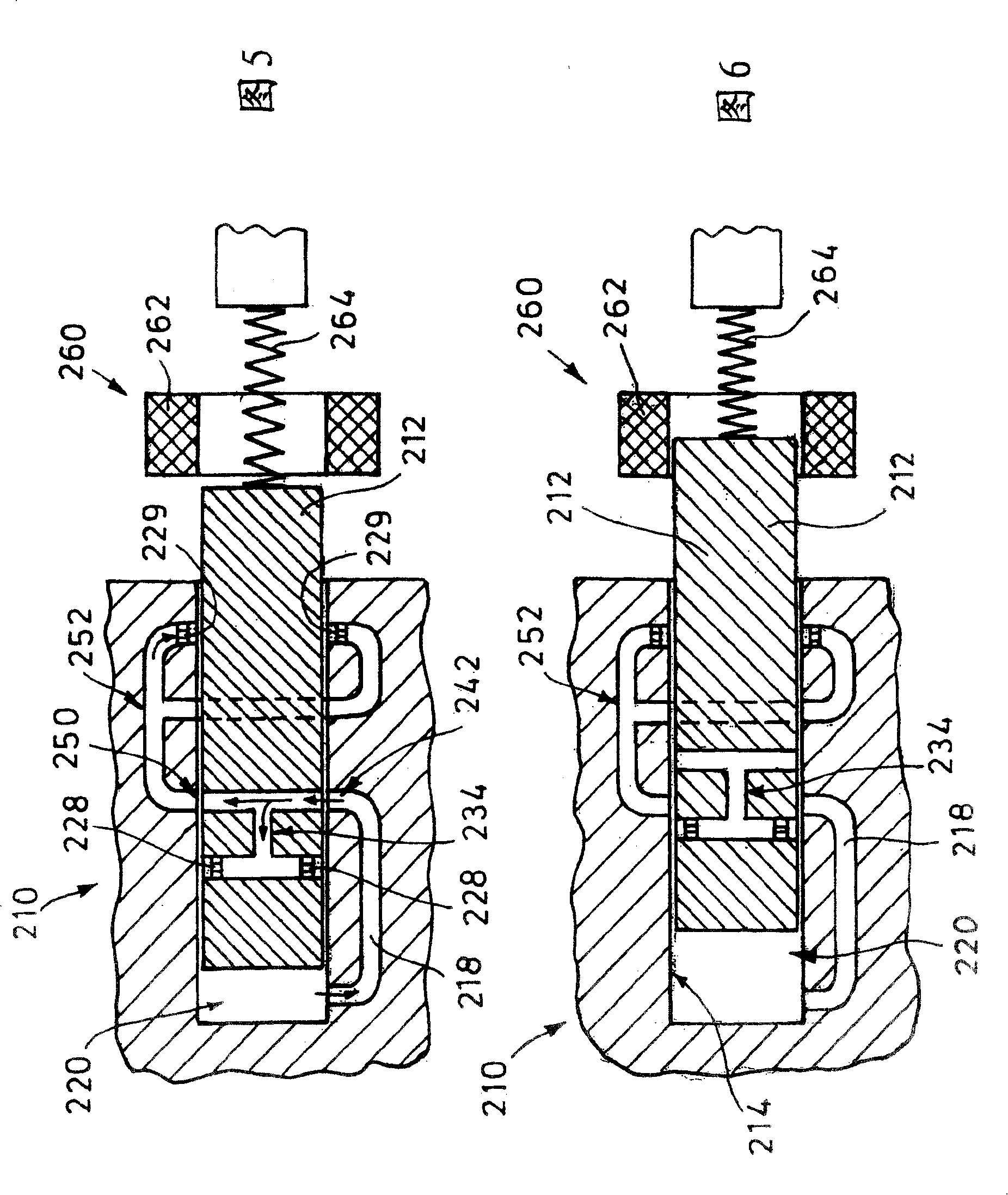
[0028] Figures 1-8 show several embodiments of piston compressors, for example used as components of a Stirling cryocooler. A Stirling cryocooler including a piston compressor is shown in Figure 9.

[0029] A first embodiment of a piston compressor 10 is shown in FIGS. 1 and 2 . Piston compressor 10 basically comprises a piston 12 oscillating within a cylinder 14 between two end positions shown in FIGS. 1 and 2 respectively.

[0030] Inside the shell 16 of the cylinder 14, there is a compressed gas supply line 18 which connects the cylinder compression chamber 20 at one end of the cylinder to a cylinder wall opening 22 in the cylinder side wall 24.

[0031] Piston 12 includes four gas bearing nozzles 28 arranged in two planes, the nozzles being connected to each other by transverse ducts 30 and longitudinal ducts 32 . At least three gas bearing no...


PUM


Abstract

A piston compressor comprises a piston (12) which reciprocates in a cylinder (14). A compressed gas supply arrangement is provided, comprising a compressed gas reservoir (34) and a compressed gas supply line (18) between a compressed gas source (20) and the compressed gas reservoir (34). Furthermore, in the course of the compressed gas supply line (18), an inlet valve (42) is provided which is open in a filling position for the piston (12). The inlet valve (42) is formed from a cylinder wall opening (22) and a piston wall opening (38), which are in mutually opposed positions in the filling position of the piston (12) and form an open valve and in a non-filling position of the piston (12) are closed by the piston wall (40) and the cylinder wall (24) and form a closed valve. A valve is thus achieved which has no moving parts and is thus simple to produce, has a high reliability and a long service life.

Description

technical field [0001] The invention relates to a piston compressor, comprising a gas bearing piston. Background technique [0002] Gas bearing piston compressors are used in particular in Stirling coolers, piston vacuum pumps and other gas compressors. The piston supported by the gas bearing in the cylinder can make the piston in the cylinder free of lubricating oil and support with low resistance. Such a piston compressor is described in WO 96 / 15369. For support on the gas bearing, the piston compressor includes a gas bearing arrangement with a compressed gas accumulator connected to the gas bearing nozzle and supplied with compressed gas at overpressure. The gas supplied by the compressed gas accumulator is, in the filling position of the piston, compressed by the piston in the compression chamber of the cylinder, with high gas pressure. To prevent the highly pressurized gas flowing from the compressed gas accumulator from flowing back into the low pressure cylinder sp...

Claims


Application Information

Patent Timeline
Patent Type & Authority Patents(China)
IPC IPC(8): F04B27/04F04B53/12F04B53/14F04B7/04F04B39/00F25B9/14
CPCF04B7/04F04B39/0016F25B9/14F04B39/0005F04B53/148F04B27/04F04B53/12F04B53/14
Inventor 诺贝尔特·罗尔夫
Owner LEYBOLD VAKUUM GMBH
Why Eureka
Eureka Blog
Learn More