Bottom valve in density pond

A dense pool and bottom valve technology, which is applied in the direction of lift valves, valve devices, engine components, etc., can solve the problems of increased handwheel operation resistance, compaction blocking the discharge port, and fast sedimentation speed, etc., to achieve small operation resistance and simple operation reasonable effect

Inactive Publication Date: 2008-07-23
CHENZHOU HENGDA SOPARATIAN MACHINERY FACTORY
View PDF6 Cites 0 Cited by
  • Summary
  • Abstract
  • Description
  • Claims
  • Application Information

AI Technical Summary

Problems solved by technology

The structure of the dense pool bottom valve in the prior art is composed of a valve stem, a valve head and a hand wheel. The upper end of the valve stem passes through the valve seat and is adjusted up and down by the hand wheel through the thread. The valve head at the lower end of the valve stem is facing the valve base of the dense pool discharge port. However, because the ore discharge procedure of the thickening tank is periodic and intermittent, and the liquid-solid ratio of the ore slurry is about 30%, the sedimentation speed is fast
Over time, it is easy to harden and block the discharge port
At the same time, the valve stem will be "sticked" by the plate agglomeration, resulting in an increase in the operating resistance of the handwheel

Method used


Image

  • Bottom valve in density pond
  • Bottom valve in density pond

Examples


Embodiment 1

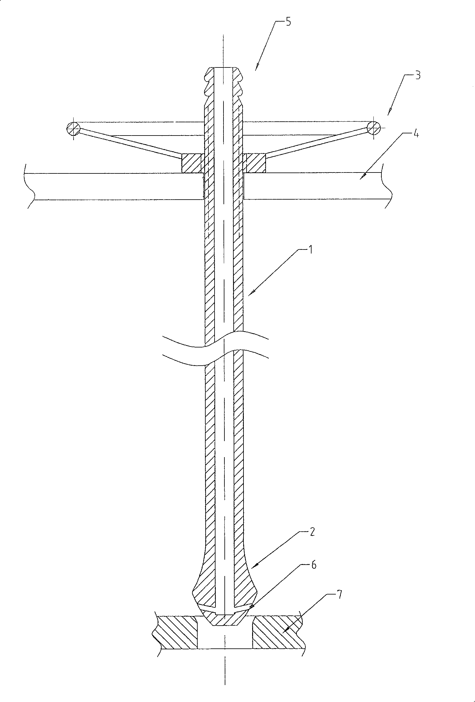
[0013] attached figure 1 Shown is a dense pool bottom valve, which is composed of a valve stem 1, a valve head 2 and a hand wheel 3. The upper end of the valve stem 1 passes through the valve seat 4 and is adjusted up and down by the hand wheel 3 through threads; the valve stem 1 is hollow Tubular structure, the top of the upper end is processed into a nozzle interface 5, and the lower end is connected with a hollow hammer-shaped valve head 2. The valve head 2 is directly above the valve base 7, and the valve base 7 is installed on the discharge port of the dense pool. There are four spray holes radiating in the horizontal direction around a section of the side of the culet.

Embodiment 2

[0015] This embodiment is a dense pool bottom valve, which is composed of a valve stem 1, a valve head 2 and a hand wheel 3. The upper end of the valve stem 1 passes through the valve seat 4 and is adjusted up and down by the hand wheel 3 through threads; the valve stem 1 is hollow. Tubular structure, the top of the upper end is processed into a nozzle interface 5, and the lower end is connected with a hollow hammer-shaped valve head 2. The valve head 2 is directly above the valve base 7, and the valve base 7 is installed on the discharge port of the dense pool. There are eight spray holes radiating toward the horizontal obliquely upward direction around a side of the bottom tip.

Embodiment 3

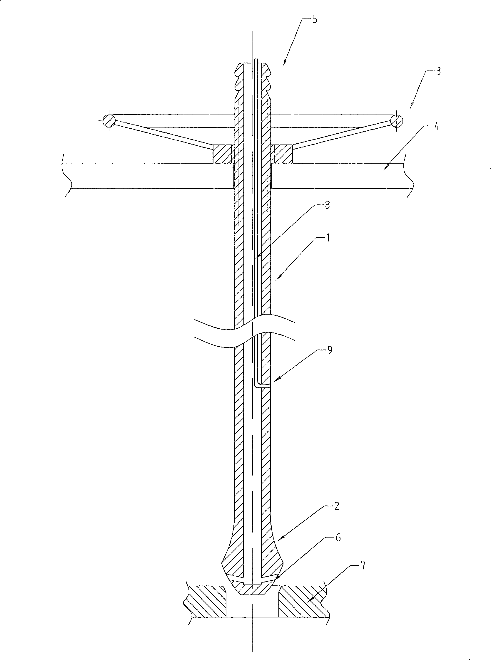
[0017] attached figure 2 Shown is a dense pool bottom valve, which is composed of a valve stem 1, a valve head 2 and a hand wheel 3. The upper end of the valve stem 1 passes through the valve seat 4 and is adjusted up and down by the hand wheel 3 through threads; the valve stem 1 is hollow Tubular structure, the top of the upper end is processed into a nozzle interface 5, and the lower end is connected with a hollow hammer-shaped valve head 2. The valve head 2 is directly above the valve base 7, and the valve base 7 is installed on the discharge port of the dense pool. There are ten spray holes radiating towards the horizontal and the horizontal obliquely upwards on a section of the side of the base. A small-diameter seamless steel pipe 8 is welded in the valve stem 1, and the lower end of the small-diameter seamless steel pipe 8 is connected to the injection hole 9 around the pipe wall of the valve stem.


PUM


Abstract

A valve used at bottom of underflow pool is featured as passing valve stem top end through valve base and using hand wheel to regulate it up and down through screw thread, setting valve stem to be hollow tubular structure and making its head of top end be pipe nozzle as well as connecting its bottom end to hollow and hammer-shaped valve head, opening a numbers of injection holes all round on side surface from valve head to bottom point and setting valve head right above valve base.

Description

technical field [0001] The invention relates to a discharge regulating valve used in an ore dressing pulp thickening tank, in particular to a thickening tank bottom valve. Background technique [0002] At present, the ore pulp produced by mineral processing is generally sent to the thickening tank for concentration treatment, and the pulp is discharged through the bottom valve of the thickening tank to reach the concentration required for mineral processing. The structure of the dense pool bottom valve in the prior art is composed of a valve stem, a valve head and a hand wheel. The upper end of the valve stem passes through the valve seat and is adjusted up and down by the hand wheel through the thread. The valve head at the lower end of the valve stem is facing the valve base of the dense pool discharge port. However, because the ore discharge procedure of the thickening pool is intermittent periodically, and the liquid-solid ratio of the ore slurry is about 30%, the sedime...

Claims


Application Information

Patent Timeline
Patent Type & Authority Patents(China)
IPC IPC(8): F16K1/02F16K51/00
Inventor 喻炳高刘巽珑
Owner CHENZHOU HENGDA SOPARATIAN MACHINERY FACTORY
Why Eureka
Try Eureka