A method for increasing production of oil and gas wells using hydration reaction hydrogen-releasing components

A technology for applying hydration and oil and gas wells, applied in the field of oil and gas well stimulation, can solve problems such as insufficient utilization of hydrogen efficiency, and achieve the effect of increasing the duration

Active Publication Date: 2017-11-21
吉林贯通能源科技有限责任公司
View PDF6 Cites 0 Cited by
  • Summary
  • Abstract
  • Description
  • Claims
  • Application Information

AI Technical Summary

Problems solved by technology

[0006] At the same time, the method described in the present invention also solves the problem of one-time violent release of hydrogen during production increase construction, resulting in insufficient utilization of hydrogen efficiency

Method used


Image

  • A method for increasing production of oil and gas wells using hydration reaction hydrogen-releasing components
  • A method for increasing production of oil and gas wells using hydration reaction hydrogen-releasing components
  • A method for increasing production of oil and gas wells using hydration reaction hydrogen-releasing components

Examples


Embodiment 1

[0061] Example 1: Hydrogenation hot gas chemical stimulation operation of Pai-684 oil well in Keshengli Oilfield, Xinjiang

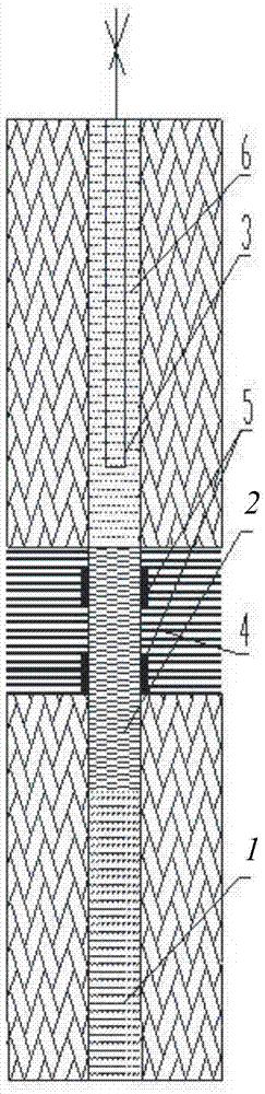
[0062] Geological conditions and related parameters of Pai-684 oil well: reservoir series sandstone and siltstone; low permeability oil layer; casing diameter ( figure 1 diameter of the oil well) Well depth (distance from surface to well bottom) 1239.4m; artificial well bottom 1239.4m; perforation range 1194-1205m; tubing diameter Before the production increase operation, the daily liquid production was 2.4t, of which the daily oil production was 1.5t;

[0063] From the above data, it can be concluded that the volume of the reaction zone is 688 liters, 379.6 liters of No. 1 solution and 308.4 liters of No. 2 solution are prepared.

[0064] No. 1 solution 493.5kg, that is, No. 1 solution is composed of 281.3kg of ammonium nitrate NH 4 NO 3 , 83.9kg of urea CO(NH 2 ) 2 , 69.1kg of nitric acid HNO 3 and 59.2kg of H 2 O composition.

[0065] No. 2...

Embodiment 2

[0079] Example 2: Hydrogenation hot gas chemical stimulation operation of Liang-113 oil well in Chunliang area, Shandong

[0080] Geological conditions and related parameters of Liang-113 oil well: the reservoir is sandstone and mudstone; it belongs to ultra-low permeability and ultra-heavy oil layer; casing diameter Well depth 2858.7m; artificial well bottom 2858.7m; perforation range 2765-2769m; tubing diameter Before the stimulation operation, the daily liquid production was 3.7t, of which the daily oil production was 2.6t; from the above data, it can be concluded that the volume of the reaction zone is 1420.2 liters. Prepare 783.6 liters of No. 1 solution and 636.6 liters of No. 2 solution.

[0081] That is, 1018.6kg of No. 1 solution, calculated by mass percentage, is composed of 607.8kg of ammonium nitrate NH 4 NO 3 , 176.6kg of urea CO (NH 2 ) 2 , 95.5kg of nitric acid HNO 3 and 138.7kg of H 2 O composition.

[0082] No. 2 solution 1018.6.kg, calculated by mas...


PUM

PropertyMeasurementUnit
melting pointaaaaaaaaaa
densityaaaaaaaaaa

Abstract

The invention belongs to the field of oil gas well exploitation and particularly relates to an oil gas well yield increase method using a hydration reaction hydrogen release component. The hydrogen release component is wrapped with capsules made of different materials and isolated from water and air, the capsules made of different materials are decomposed at different temperatures, and a reactant starts to react and release hydrogen and thermal energy. The method can control release amount and release time of hydrogen, and also solves the problem that in yield increase consecution, hydrogen is violently released at a time and accordingly efficiency of hydrogen is not fully used. When an area near a well is heated through energy released by downhole reaction of a first solution and a second solution, the generated energy is released outwards in a gas pulse mode, and paraffin, asphaltene and other organic macromolecular blocking materials are subjected to catalytic cleavage reaction at high temperature, so that blocking materials in an oil way are removed, permeability is increased, and the aim of resuming production is achieved.

Description

technical field [0001] The invention belongs to the technical field of oil and gas well exploitation, and in particular relates to a method for increasing production of an oil and gas well using a hydrogen-releasing component in a hydration reaction. Background technique [0002] The recovery capacity of an oil well depends on many factors, such as the rock properties and porosity of the production layer, the effective oil layer thickness of the production layer, the permeability of the formation, the viscosity of crude oil, the oil saturation and water saturation of the oil layer, the original pressure of the production layer and the oil layer, etc. . In addition, the deposition and attachment of paraffin and asphalt-containing colloidal substances (AFS) near the wellbore is also an important factor affecting the recovery factor. [0003] At present, the methods of enhancing oil recovery can be roughly divided into chemical methods, physical methods, thermal methods and mi...

Claims


Application Information

Patent Timeline
Patent Type & Authority Patents(China)
IPC IPC(8): E21B43/16C01B3/02
CPCC01B3/02C01B2203/0272E21B43/168
Inventor 韩晓松西莫年科·阿列克谢韩炜周亮
Owner 吉林贯通能源科技有限责任公司
Why Eureka
Try Eureka