
Bus type connection system for backplanes

A technology for connecting systems and buses, which is applied in the field of bus-type connection systems, and can solve the problems of transmission signal distortion and frequency limitation of signal transmission, etc.

Inactive Publication Date: 2008-07-23
ALCATEL LUCENT SAS
View PDF4 Cites 0 Cited by
  • Summary
  • Abstract
  • Description
  • Claims
  • Application Information

AI Technical Summary

Problems solved by technology

These phenomena cause distortion of the transmitted signal, limiting the frequency at which the signal can be transmitted

Method used


Image

  • Bus type connection system for backplanes
  • Bus type connection system for backplanes
  • Bus type connection system for backplanes

Examples


Embodiment Construction

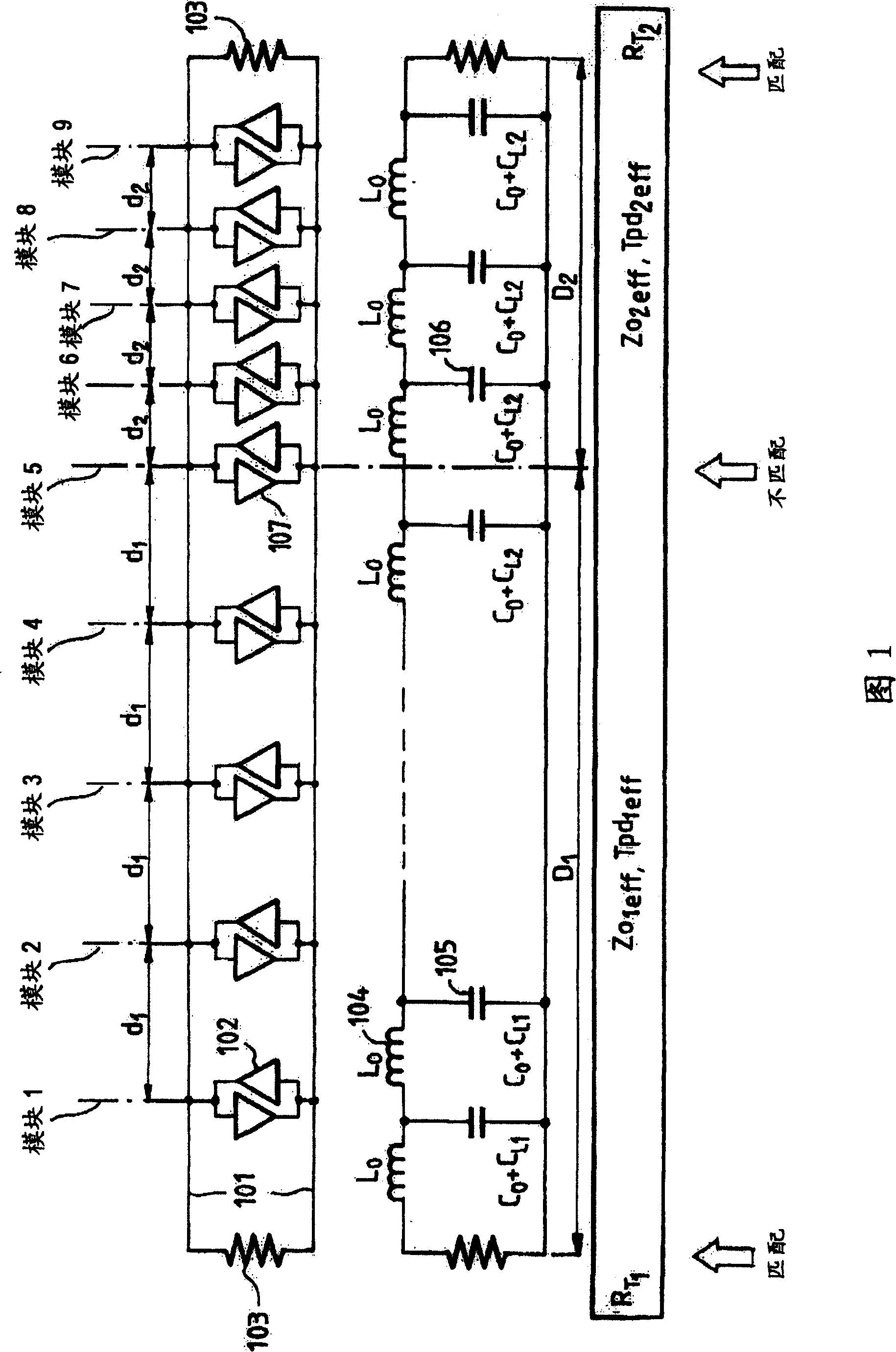
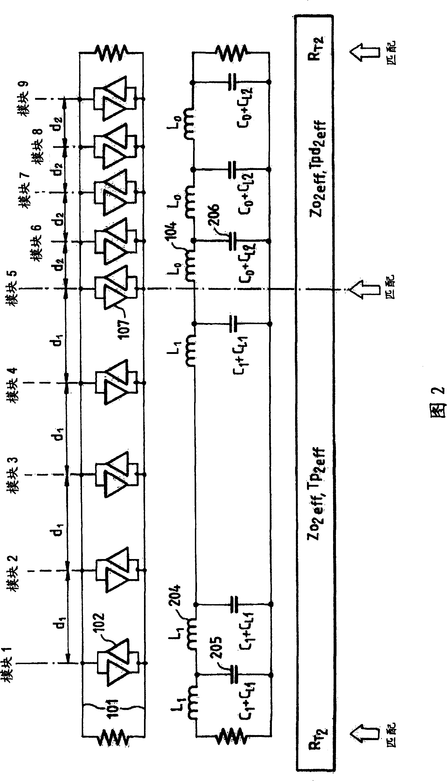
[0018] FIG. 1 schematically shows a particular embodiment of the invention, which corresponds to a backplane bus with a total length D1+D2=75 centimeters (cm). For ease of explanation, only one line is shown associated with a signal, although it should be understood that a bus will generally include many lines, in which case the invention applies in the same manner to each line of the bus.

[0019] In order to use the above-mentioned bus at a frequency of 40MHz, certain technologies need to be adopted, such as the strip-line technology using wires, so the form of a transmission line with a distributed constant is adopted, and its characteristic impedance is determined by the following parameters Determine, for example: L0 = 4.73 nanoseconds / centimeter (nH / cm); C0 = 1.06 picofarads / centimeter (pF / cm); Z0 = 67 ohms (Ω); Tpd = 70.7 picoseconds / centimeter (ps / cm)

[0020] The physical representation of the upper part of the figure shows a set of input / output buffer amplifiers 102 ...


PUM


Abstract

The invention relates to bus type connection systems, in particular those for wiring backplanes of electronic systems, when the bus comprises connectors distributed in an irregular manner. It consists in selecting segments (D1, D2) over which the intervals (d1, d2) between the connectors are substantially constant. The structure of all the segments except one is then modified to make the effective impedance of the modified segments coincide with that of the unmodified segment. It produces a bus that is fully matched from end to end and able to operate at a very high frequency with a slight reduction of its propagation constant.

Description

technical field [0001] The present invention relates to a connection system of the bus type, that is to say a connection system comprising one or more pairs of two wire lines in which connectors for connecting electronic devices can be located anywhere on the lines. [0002] The information propagated on the line is sent and received on the bus with the help of a coding system, generally a time coding system, which determines the device to which the currently transmitted information is related. A bus usually consists of a set of wires used to transfer information in parallel. This system is widely used in personal computers (PCs) to connect expansion cards. It is also widely used in dedicated electronic equipment for the wiring of the backplane into which the circuit cards making up the required hardware are plugged. Background technique [0003] The connectors are usually fixed on the backplane at equal intervals, and they are connected by electrical wires, and the wires ...

Claims


Application Information

Patent Timeline
Patent Type & Authority Patents(China)
IPC IPC(8): G06F13/38G06F13/40G06F17/50
CPCG06F13/409G06F17/5045G06F17/5036G06F30/367G06F30/30
Inventor 塞巴斯蒂安·纪尧姆
Owner ALCATEL LUCENT SAS
Learn More