Reciprocating piston pumps with flow-through plain bearings

A reciprocating, plunger pump technology, applied in the direction of variable capacity pump components, pumps, pump components, etc., can solve problems such as quantitative pump wear and tear

Inactive Publication Date: 2015-12-02
THOMAS MAGNETE GMBH
View PDF12 Cites 0 Cited by
  • Summary
  • Abstract
  • Description
  • Claims
  • Application Information

AI Technical Summary

Problems solved by technology

[0003] With the promotion of fuels that are not based on mineral oil, such as for example biodiesel or alcohol, and therefore also have a relatively high proportion of water, the materials of the friction partners, especially the material of the plunger and the cylinder block material has to be adjusted; however, under certain operating conditions, new wear phenomena are still encountered in such fixed displacement pumps

Method used


Image

  • Reciprocating piston pumps with flow-through plain bearings
  • Reciprocating piston pumps with flow-through plain bearings
  • Reciprocating piston pumps with flow-through plain bearings

Examples


Embodiment Construction

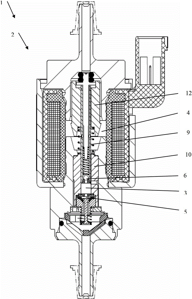
[0049] A reciprocating plunger pump 1 driven by an electromagnet 2 contains two check valves 5 and 6 and also contains a plunger 9 which is hermetically housed in a cylinder 10 and supports the armature post of the electromagnet 2 stuffed.

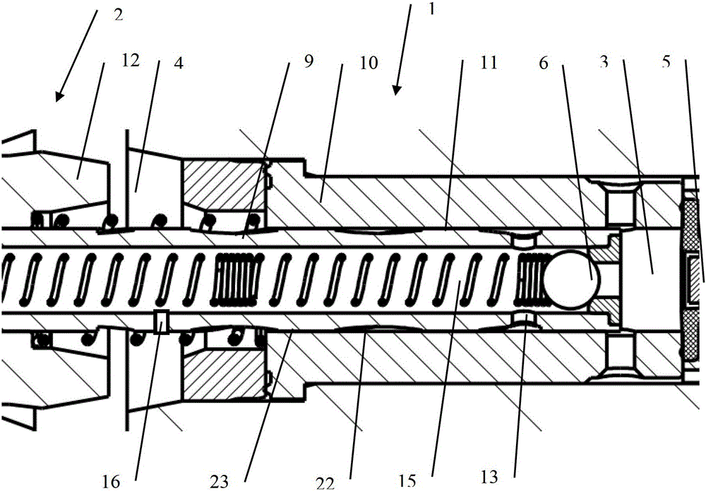
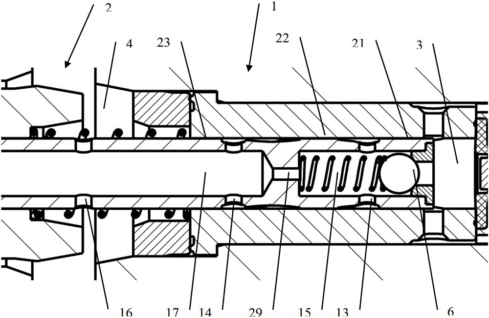
[0050] figure 2 It is shown that an elongated recess is provided in one of the two surfaces of the bearing gap 11 between the plunger 9 and the cylinder 10, through which recess the conveyed liquid flow flows. For this purpose, the transverse bore 13 creates a connection from the valve 6 to the bearing gap 11 .

[0051] in accordance with figure 2 In the first and second embodiments of the reciprocating plunger pump 1 the liquid flow from the valve 6 is guided wholly or partly via the transverse hole 13 into a recess in the surface of the plunger 9 or in the surface of the cylinder 10 , and is guided into the armature chamber 4 via the bearing areas 22 and 23 , wherein the recess extends into the armature chamber 4 and does not extend...


PUM


Abstract

A reciprocating-piston pump with plain bearing traversed by flow. The reciprocating-piston pump is driven by an electromagnet to have a bearing of the piston in a cylinder, which bearing is protected against local overheating and from which bearing decomposition and reaction products and any wear products generated are discharged. For this purpose, elongate helical depressions are provided in one of two bearing surfaces in a bearing gap between the piston and the cylinder, which depressions are traversed entirely or partially by a flow of the liquid which is delivered by the piston acting in interaction with other components of the reciprocating-piston pump for the delivery rate of the reciprocating-piston pump. Reciprocating-piston pumps of the described type can be used as dosing pumps and as delivery pumps in fuel-operated standstill heaters, auxiliary heaters and exhaust-gas purification systems in vehicles.

Description

technical field [0001] The invention relates to a reciprocating piston pump driven by an electromagnet, corresponding to the preamble of claim 1 . Background technique [0002] Reciprocating plunger pumps driven by electromagnets for conveying and dosing fuel are known, tried and tested, for example from DE 4328621 and DE 10 2001 111 926 . [0003] With the promotion of fuels that are not based on mineral oil, such as for example biodiesel or alcohol, and therefore also have a relatively high proportion of water, the materials of the friction partners, especially the material of the plunger and the cylinder block The material has to be adjusted; however, under certain operating conditions new wear phenomena are still encountered in such fixed displacement pumps. Wear phenomena are caused, for example, by local overheating if locally limited lubricant film failure occurs, or by reduced lubricating properties associated with media based solely on mineral oil. [0004] From d...

Claims


Application Information

Patent Timeline
Patent Type & Authority Patents(China)
IPC IPC(8): F04B17/04F04B13/00
CPCF04B17/03F04B17/046F04B39/06F04B39/02F04B39/0276
Inventor 米夏埃尔·费克勒米凯·黑克阿克塞尔·米勒奥拉夫·奥利克施莱格特贝阿·赖因施密特罗伯特·韦尔尼茨
Owner THOMAS MAGNETE GMBH
Why Eureka
Try Eureka