

High building life saving device
A technology for life-saving devices and high-rise buildings, applied in life-saving equipment, building rescue, etc., can solve the problems of being unsuitable for the elderly, patients, infants, and low efficiency, and achieve the effects of simple structure, stable transmission, and firm connection
- Summary
- Abstract
- Description
- Claims
- Application Information
AI Technical Summary
Problems solved by technology
Method used
Image

Examples
specific Embodiment approach 1
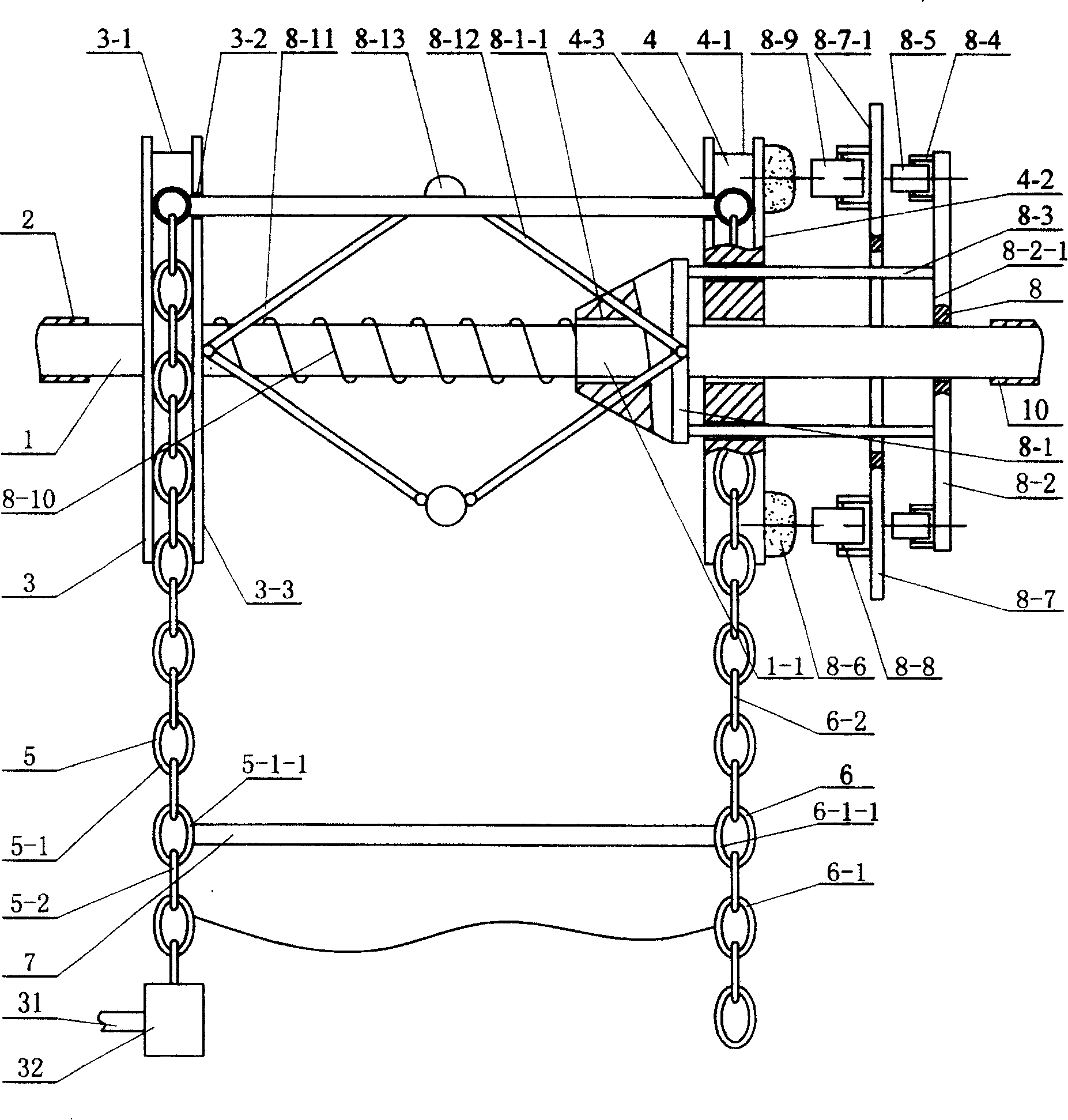
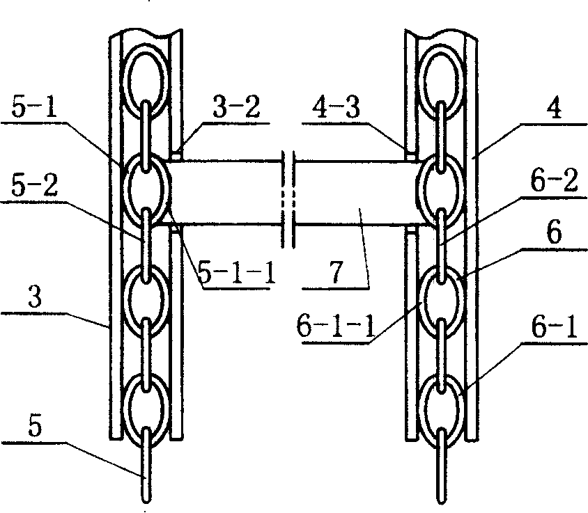
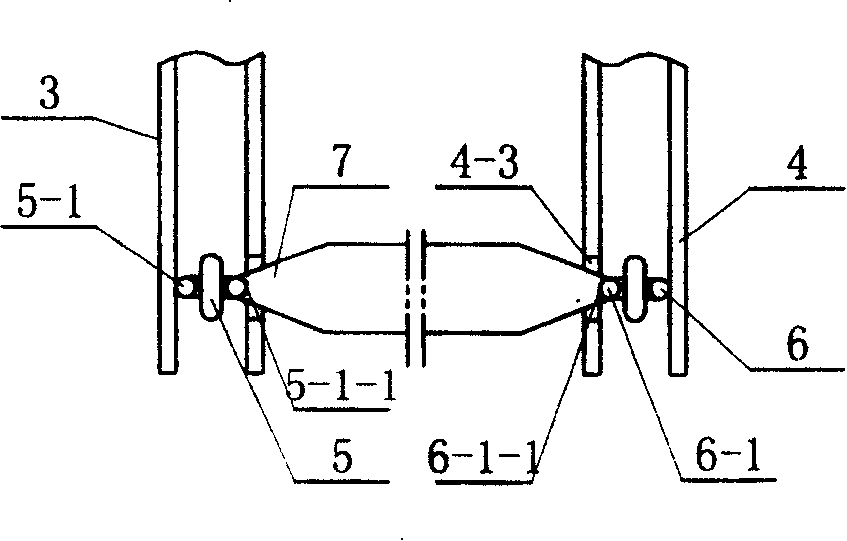
[0006] Specific implementation mode 1: Combination figure 1 , Figure 8 To describe this embodiment, this embodiment consists of a rotating shaft 1, a first sliding bearing 2, a second sliding bearing 10, a left sprocket 3, a right sprocket 4, a left chain 5, a right chain 6, a cross bar 7, and a damping device 8 or centrifugal device 9; the two ends of the rotating shaft 1 are equipped with a first sliding bearing 2 and a second sliding bearing 10, respectively, and a left sprocket is installed on the rotating shaft 1 inside the first sliding bearing 2 and the second sliding bearing 10, respectively 3 and right sprocket 4; the outer end of the left sprocket 3 has a left groove 3-1, the outer end of the right sprocket 4 has a right groove 4-1, and the left groove 3-1 is equipped with a left chain 5. The right ring chain 6 is installed in the right groove 4-1, the left ring chain 5 is meshed with the tooth in the left groove 3-1, and the right ring chain 6 is meshed with the tooth ...
specific Embodiment approach 2
[0007] Specific implementation manner two: combination figure 1 To explain this embodiment, the difference between this embodiment and the first embodiment is: the damping device 8 of this embodiment is composed of a sliding sleeve 8-1, a side plate 8-2, a flat tie rod 8-3, and a fixed sleeve 8-4. , Outer roller 8-5, sand bag 8-6, blocking plate 8-7, jacket 8-8, inner roller 8-9, spring 8-10, left connecting rod 8-11, right connecting rod 8-12, The centrifugal weight 8-13 is composed; the left end shaft 1 of the right sprocket 4 is equipped with a sliding shaft sleeve 8-1, and the right end shaft 1 of the right sprocket 4 is equipped with a side plate 8-2, a sliding shaft sleeve 8-1 and a side plate A set of flat tie rods 8-3 is fixed between 8-2, the fixing sleeve 8-4 of the left end of the side plate 8-2 8-2-1 is equipped with an outer roller 8-5, and the right end of the right sprocket 4 4- 2 is fixed with a sand bag 8-6, a blocking plate 8-7 is arranged between the right spro...
specific Embodiment approach 3
[0008] Specific implementation mode three: combination Figure 8 To explain this embodiment, the difference between this embodiment and the first embodiment is: the centrifugal device 9 of this embodiment consists of a left sleeve 9-1, a right sleeve 9-2, a compression spring 9-3, and a heavy wheel 9- 4. The left tie rod 9-5, the right tie rod 9-6, the sand bag 9-11, and the bracket 9-12 are composed; the shaft 1 between the left sprocket 3 and the right sprocket 4 is respectively equipped with a left sleeve 9-1 And the right shaft sleeve 9-2, the shaft 1 between the left shaft sleeve 9-1 and the right shaft sleeve 9-2 is equipped with a compression spring 9-3, and the right end surface 9-1-1 of the left shaft sleeve 9-1 is connected to the left The left end of the tie rod 9-5 is hinged, the left end surface 9-2-1 of the right shaft sleeve 9-2 is hinged with the right end of the right tie rod 9-6, the right end of the left tie rod 9-5 and the left end of the right tie rod 9-6 are r...
PUM
 Abstract
Description
Claims
Application Information