Leakproof pattern plate

A formwork and leak-proof technology, applied in the field preparation of formwork/formwork components and building components, construction, etc., can solve the problem of single, can not solve the leak-proof problem, etc., achieve low cost, prolong the leakage path, improve the construction holistic effect

Inactive Publication Date: 2008-09-03
汪荣勋
View PDF7 Cites 0 Cited by
  • Summary
  • Abstract
  • Description
  • Claims
  • Application Information

AI Technical Summary

Problems solved by technology

[0003] The existing formwork is strip-shaped, and its front is usually a single plane, and there are also curved or right-angled planes on the front. This type of formwork is mainly used for casting corner parts, but none of them can solve the problem of leak prevention

Method used


Image

  • Leakproof pattern plate
  • Leakproof pattern plate
  • Leakproof pattern plate

Examples


Embodiment Construction

[0035] Figure 25 Shown is a schematic diagram of the structure of the existing formwork. The common formwork 101 is strip-shaped, and its front is a single plane, which is used for the parts connected with the surfaces of the main bodies of the concrete columns. Can also be used when pouring quarter corners. The other is the external corner special-shaped formwork 102, which is mainly used for pouring convex right-angle corner parts. On the other hand, there is also a special-shaped formwork 103 for female corners, which is mainly used for pouring concave right-angle corners. There is also a curved formwork, which is mainly used for casting curved corners. The defects of this type of template have been described above, and will not be repeated here.

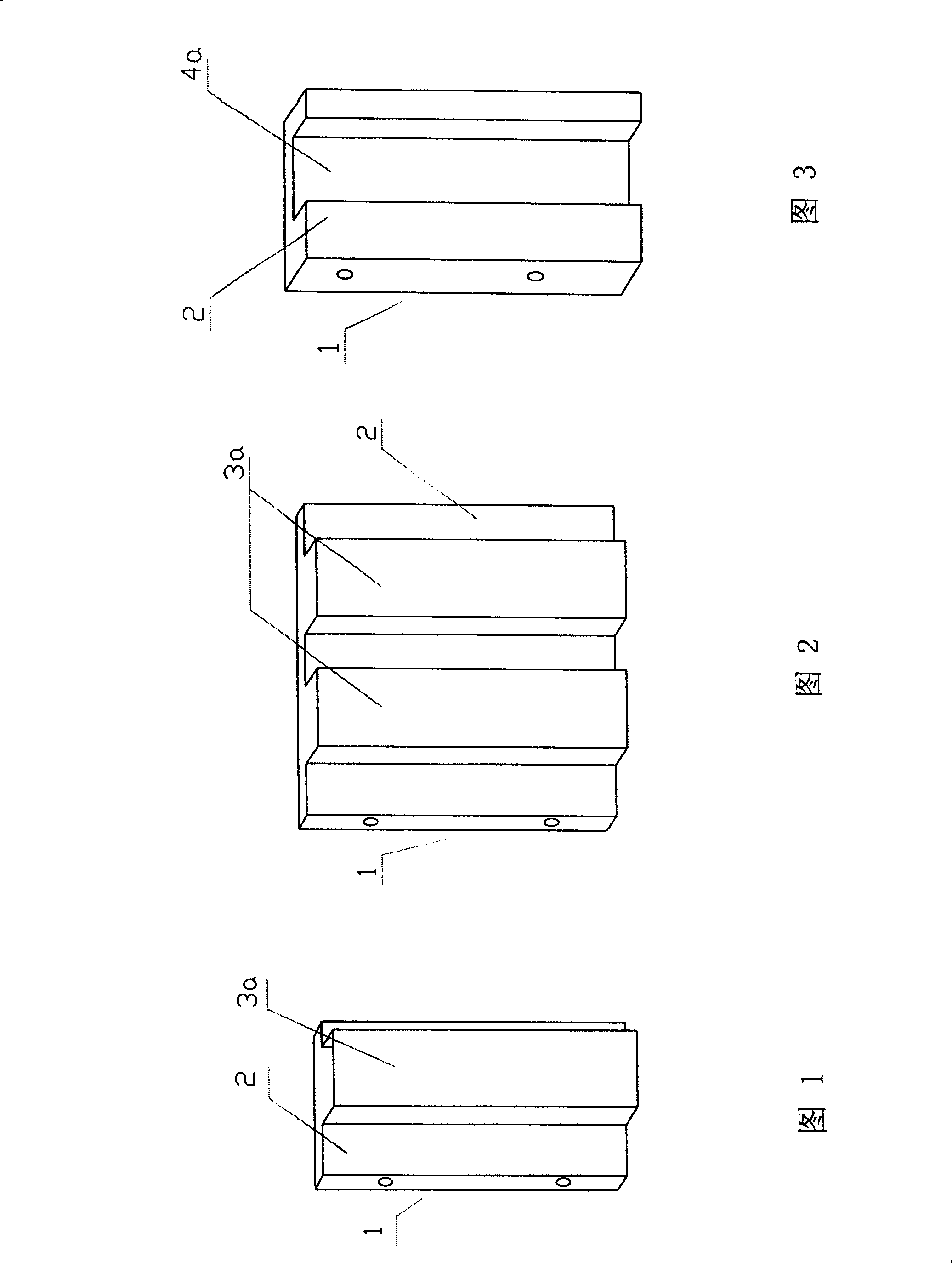
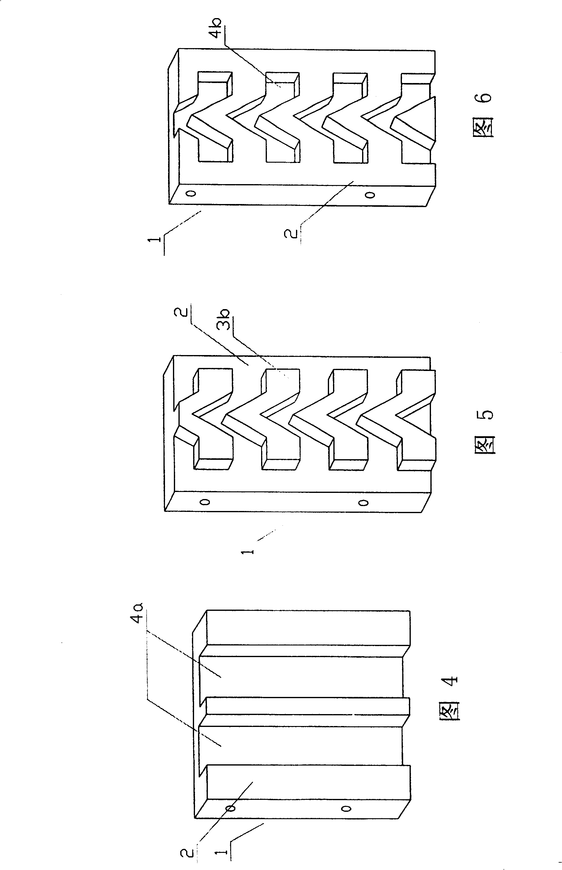
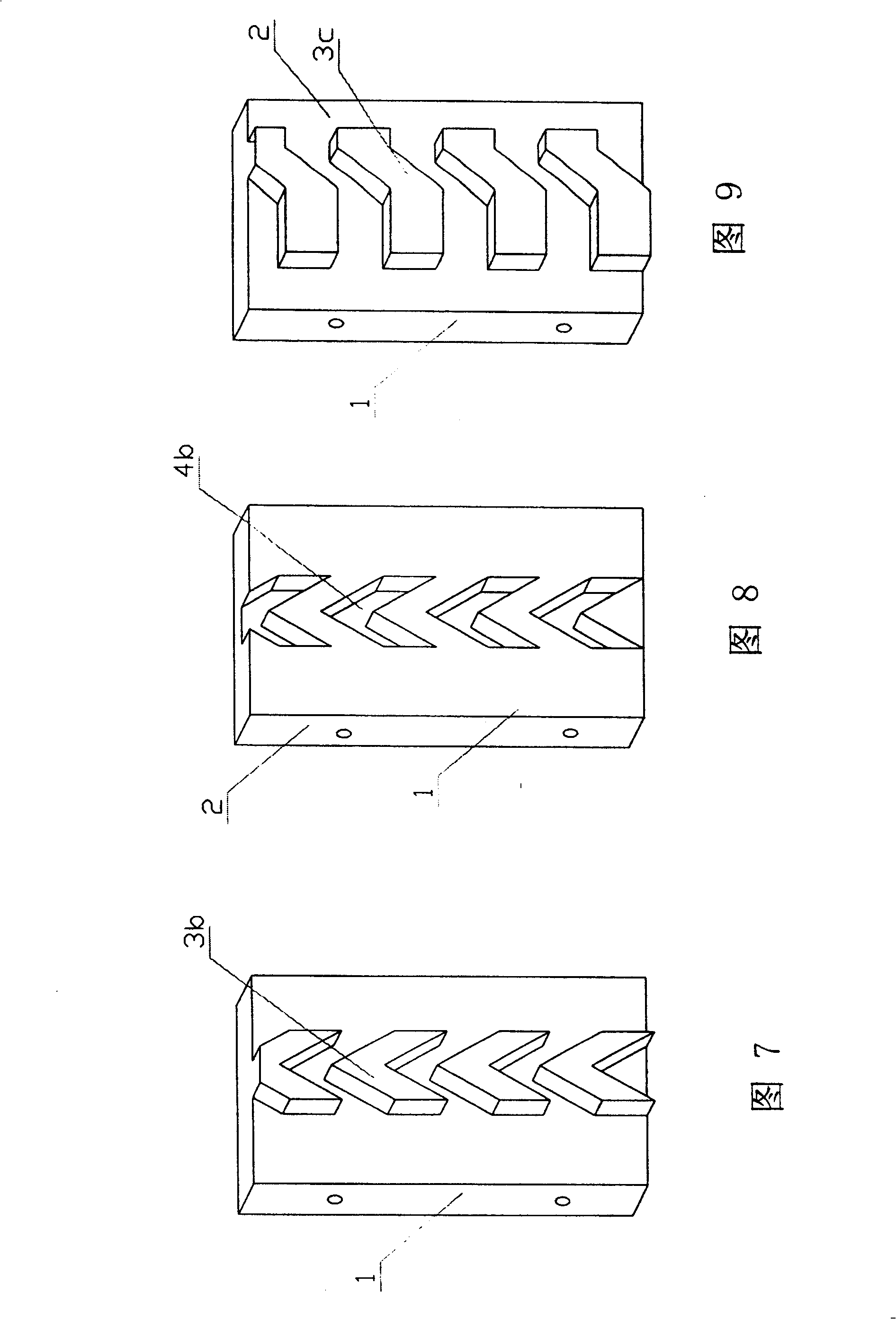
[0036] Referring to Fig. 1 to Fig. 12, the leak-proof formwork of the present invention has ribs or grooves matching the shape of the block on the front side 2 of the body 1 . The rib is a single rib 3a running through the le...


PUM


Abstract

This invention discloses a leakproofing framework. It includes the framework which front face is designed a convex arris or groove to match the shape of building blocks. The convex arris or groove are lengthwise strip convex arris or run-through groove. The strip and sectional groove can be a shape of square, triangle, trapezoid or arc. The convex arris or groove can be a structure like horse teeth, which single unit should be a 'lembada' shape, trapezoid or slope. On the surfaces of concrete poles or beams of form casting of this invention will appear proper grooves or the convex arrises which closely bond with the tops of building blocks, so it can reduce the chances of splitting between the bonding body and concrete poles, improve the building cohesion and minish the leakage in the joint of the bonding body and concrete poles. Therefore, this invention can minimize or entirely solve the leakage resulting from the splitting, and it is easily operated and costs lower.

Description

technical field [0001] The invention relates to a building formwork, in particular to a leak-proof formwork. Background technique [0002] Cracks often occur at the joints between masonry and columns and beams in buildings, which affects the integrity and quality of the building; cracks are prone to water leakage, especially in rainy areas. The prior art is: the connection between the column and the masonry generally adopts the steel bars extending from the column to connect the masonry, and the bottom of the beam generally does not have the measure of stretching out the steel bars to connect with the masonry. These methods increase the cost, and the construction is not very convenient, especially the problem of cracking and water leakage at the joint between the bottom of the beam and the masonry can not be solved well so far. [0003] Existing templates are in the shape of strips, and the front is usually a single plane, and there are also curved or right-angled planes on...

Claims


Application Information

Patent Timeline
Patent Type & Authority Patents(China)
IPC IPC(8): E04G9/10
Inventor 汪荣勋
Owner 汪荣勋
Why Eureka
Try Eureka