
Water supply apparatus

A technology for water supply and power generation units, which is applied in water supply installations, indoor sanitary piping installations, and hydroelectric power generation, etc., can solve the problems of generator power loss, hindering blade rotation, and complicated operations.

Active Publication Date: 2008-09-03
TOTO LTD
View PDF6 Cites 0 Cited by
  • Summary
  • Abstract
  • Description
  • Claims
  • Application Information

AI Technical Summary

Problems solved by technology

And, although the water flowing into the base end portion of the blade has the effect of rotating the blade a little, it also acts as the rotation resistance of the blade, which hinders the rotation of the blade instead, resulting in a loss of power generation of the generator.
[0009] Also, in conventional devices, since the rotating shaft is mounted on the device main body, rather than the structure in which the power generation unit is detachably mounted on the device main body, the power generating mechanism such as the rotating shaft or blades is assembled into the device. The work on the main body is cumbersome, and the maintenance work of the power generating mechanism is also cumbersome.

Method used


Image

  • Water supply apparatus
  • Water supply apparatus
  • Water supply apparatus

Examples


Embodiment Construction

[0036] Hereinafter, a specific structure of the water supply device of the present invention will be described with reference to the drawings.

[0037] (toilet flushing device)

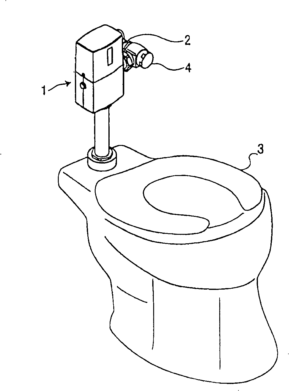
[0038] figure 1 A toilet flushing device 1 as a water supply device of the present invention is shown.

[0039] Toilet flushing device 1 such as figure 1 As shown, it is installed between the water supply pipe 2 and the toilet 3 , and the water supplied from the water supply pipe 2 is supplied to the toilet 3 . Among the figure, 4 is a stop valve plug. In addition, the toilet 3 can be figure 1 The toilet shown, can also be Figure 11 The urinal shown.

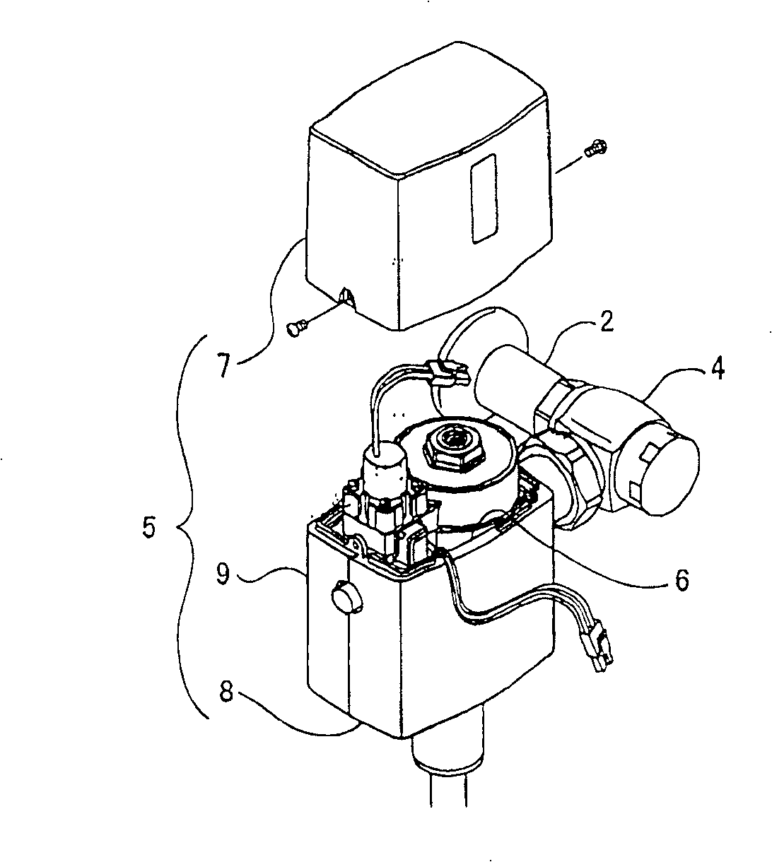
[0040] The toilet flushing device 1 such as figure 2 As shown, the device main body 6 is arranged inside the housing 5 .

[0041] Shell 5 as figure 2 , Figure 4 and Figure 5 As shown, it is composed of an upper cover 7 covering the upper part of the device main body 6, a front cover 8 covering the front lower part of the device main body...


PUM


Abstract

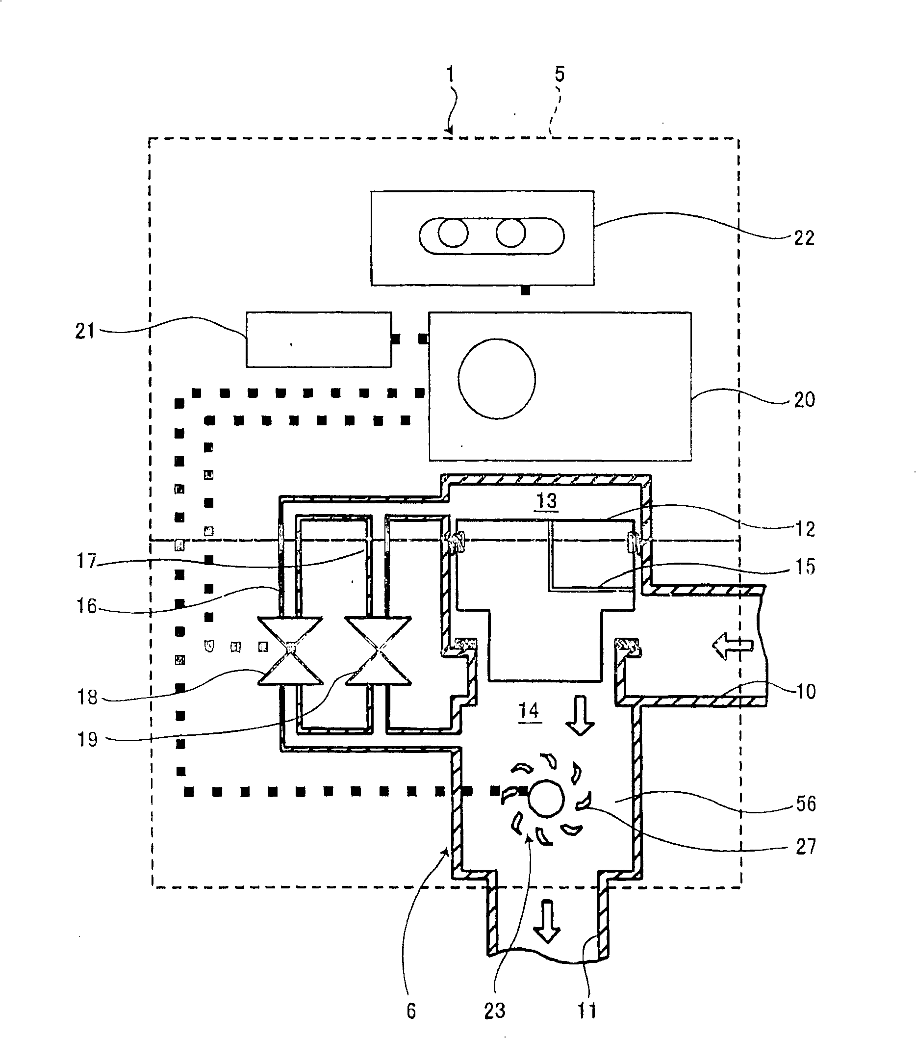
The present invention provides a water supply apparatus, comprising an apparatus body (6) disposed in a flow passage (14) for sucking water to an indoor facility and a power generation unit (23) installed in the apparatus body, the power generation unit further comprising a rotating shaft (34) extended in a direction perpendicular to the water channel direction of the flow passage, an impeller (27) installed on the rotating shaft and rotated by water flow, a magnet (43) rotated interlockingly with the impeller, and a coil (29) arranged oppositely to the magnet, wherein the impeller forms blades (38) in the radial outer direction and forms clearances (40) allowing water to pass to the inside of the blades. Since the clearances (40) are formed between the blades (38) and the rotating shaft (34), such a trouble that water flowing into the base ends of the blades obstructs the rotation of the impeller can be eliminated to increase a power generation amount by the power generation unit. In addition, since there is no need to expand the flow passage on the outside of the impeller to reduce the rotational resistance of the impeller, the size of the water supply apparatus can be reduced.

Description

technical field [0001] The present invention relates to a water supply device in which a power generation unit is provided on the way of a flow path for supplying water to indoor equipment. In addition, indoor equipment refers to public facilities such as offices and stations, or water surrounding equipment such as washstands, washstands, toilets, washing machines, etc. used in houses, that is, equipment that uses upper water, reclaimed water, sewage, well water, rainwater, etc. . Background technique [0002] Conventionally, a water supply device provided with a power generating unit in the middle of a flow path of water supply to indoor equipment has been widely used. In this water supply device, the water flow in the flow path is used to generate electricity by the power generation unit, and the generated power drives various electronic devices such as sensors and switches installed inside or outside the water supply device. [0003] For example, in the automatic water ...

Claims


Application Information

Patent Timeline
IPC IPC(8): F03B1/00F03B13/00E03C1/05E03D5/10
CPCY02E10/223Y02E10/20
Inventor 藤本英史小野寺尚幸中山公博畠山真榎本和幸工藤幸广久我达弘石丸仁志
Owner TOTO LTD
Learn More