Method and device for controlling drive unit

A drive unit and control unit technology, applied in electrical control, engine control, fuel injection control, etc., can solve problems such as no optimal results and limitations, and achieve the effects of improving monitoring accuracy, improving usability, and fast fault response

Inactive Publication Date: 2008-10-01
ROBERT BOSCH GMBH
View PDF7 Cites 0 Cited by
  • Summary
  • Abstract
  • Description
  • Claims
  • Application Information

AI Technical Summary

Problems solved by technology

This requirement is limited when this component is miscalculated
[0006] The above known solutions do not give the best results for all cases

Method used


Image

  • Method and device for controlling drive unit
  • Method and device for controlling drive unit
  • Method and device for controlling drive unit

Examples


Embodiment Construction

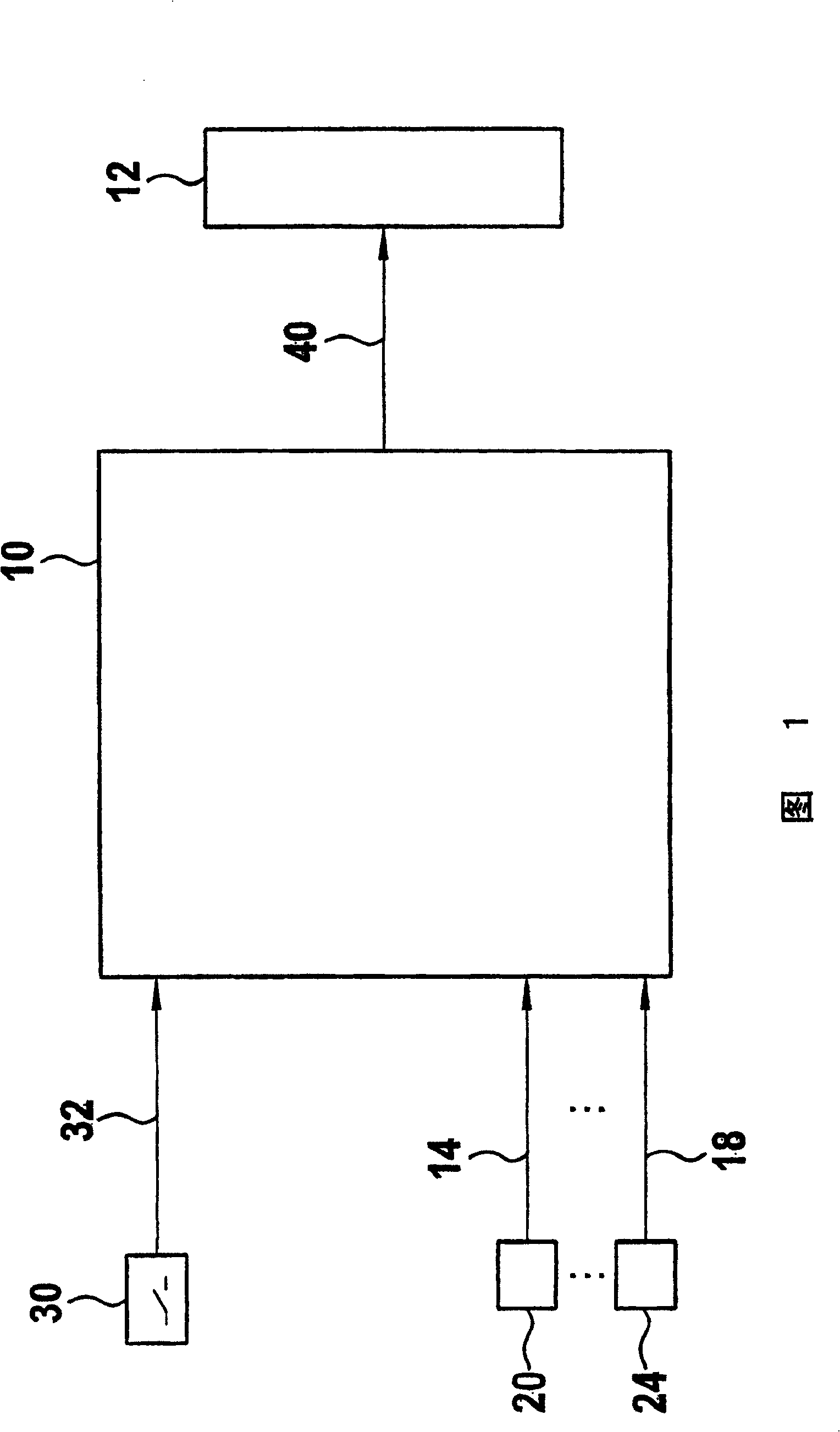
[0020] FIG. 1 shows a control unit 10 for controlling a drive unit 12 , wherein the control unit 10 includes at least one computer with a memory in which a program for controlling the drive unit 12 is stored. For the execution of the program, operating parameter signals of the drive unit and / or the vehicle are supplied via the input lines 14 to 18 of the corresponding measuring devices 20 to 24 to a computer, which calculates the operating parameter signal and forms an adjustment signal for at least one drive unit 12 . Such operating parameter signals are, for example, signals representing engine temperature, accelerator pedal position and the like.

[0021] The input parameter delivered to the control unit 10 is converted into at least one adjustment parameter by a program running in the computer, which controls the at least one control unit 12 of the drive unit 12 via the at least one output lead 40 of the control unit 10 in the name of the input parameter. state parameters...


PUM


Abstract

The invention relates to a method and device for controlling a drive unit in which a maximum permissible value of an output quantity is determined. This value is compared with the actual value, and reaction measures are initiated when the maximum permissible value is exceeded by the actual value. The maximum permissible value is filtered at least in one operating state according to a filtering means comprising a filter and a dead zone element. In addition, the maximum permissible value is continuously reduced according to the convergence of at least one quantity, which represents an operating state, to a limiting value.

Description

technical field [0001] The invention relates to a method and a device for controlling a drive unit. Background technique [0002] A method of this type as well as a device of this type are known from DE 195 36 038 A1 (US patent 5 692 472). There, in the context of controlling the drive unit of the vehicle, for monitoring purposes, the value representing the output variable of the drive unit is compared with a specified maximum permissible value for this value, and error response measures are initiated if the value exceeds this specified permissible value. For example, the output parameter of the drive unit is the power of the drive unit or the torque of the drive unit, such as indicated torque, output torque and the like. In one embodiment, the computer executing the control of the drive unit comprises at least two mutually separate program levels, wherein the comparison for monitoring is calculated in the second program level. The program reserves this first program level...

Claims


Application Information

Patent Timeline
Patent Type & Authority Patents(China)
IPC IPC(8): F02D41/02F02D41/08F02D45/00
CPCF02D2250/26F02D2250/18F02D41/021F02D41/08
Inventor F·普拉格R·敦克T·保尔F·贝德尔纳B·施泰恩曼
Owner ROBERT BOSCH GMBH
Why Eureka
Try Eureka