Supercharge Your Innovation With Domain-Expert AI Agents!

Connection structure adjecent front verticlal pole of vehicle

A technology for connecting structures and uprights, which is applied in the directions of superstructure, superstructure sub-assemblies, vehicle components, etc., to reduce vehicle weight, reduce production costs, and improve driving stability.

Inactive Publication Date: 2008-10-08
MITSUBISHI MOTORS CORP
View PDF6 Cites 0 Cited by
  • Summary
  • Abstract
  • Description
  • Claims
  • Application Information

AI Technical Summary

Problems solved by technology

[0008] In the connection structure near the front pillar of the vehicle disclosed in Japanese Patent Document 1, there is still room for further improvement in the rigidity of the vehicle body and the rigidity of the bracket. Therefore, it is desired to provide a new connection structure near the front pillar of the vehicle body.

Method used


Image

  • Connection structure adjecent front verticlal pole of vehicle
  • Connection structure adjecent front verticlal pole of vehicle
  • Connection structure adjecent front verticlal pole of vehicle

Examples


Embodiment Construction

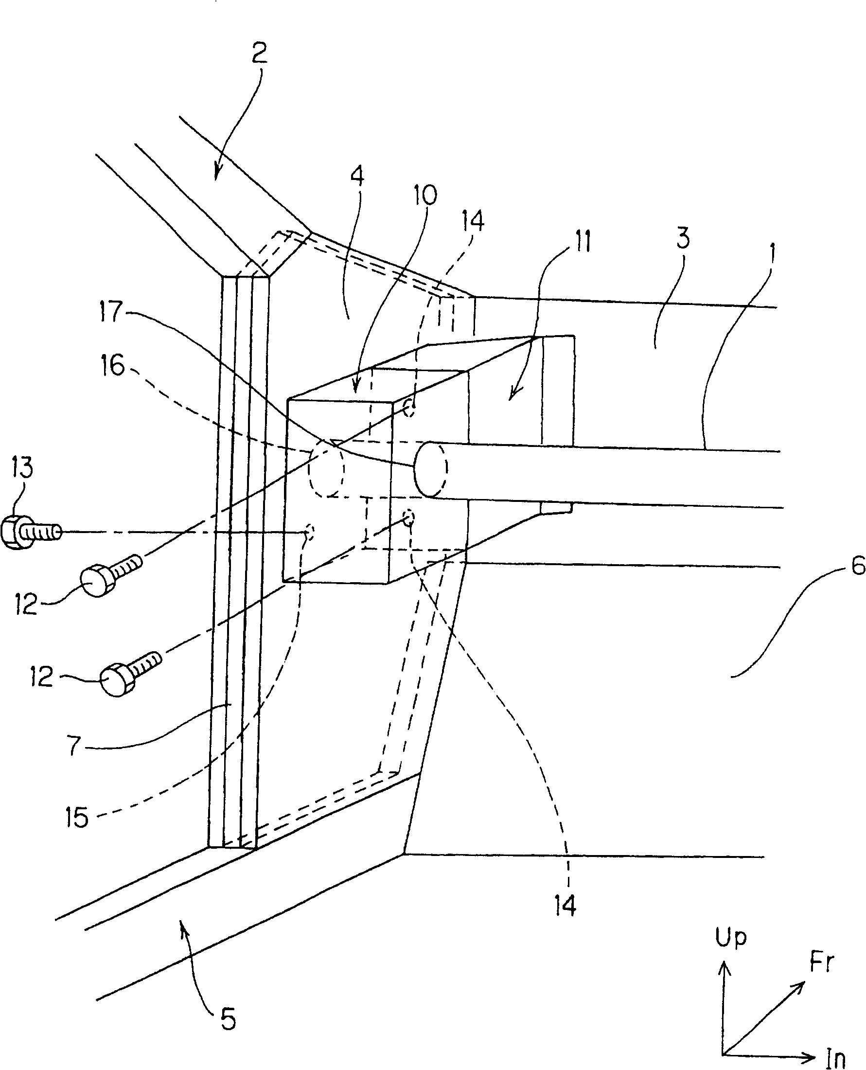
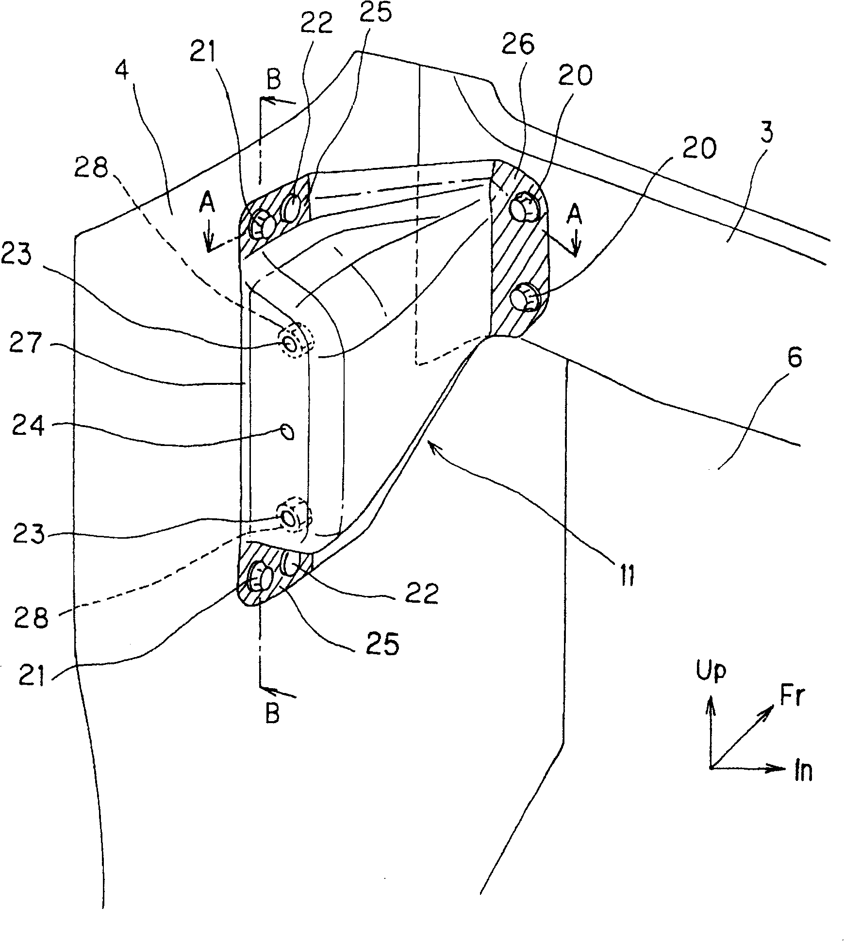
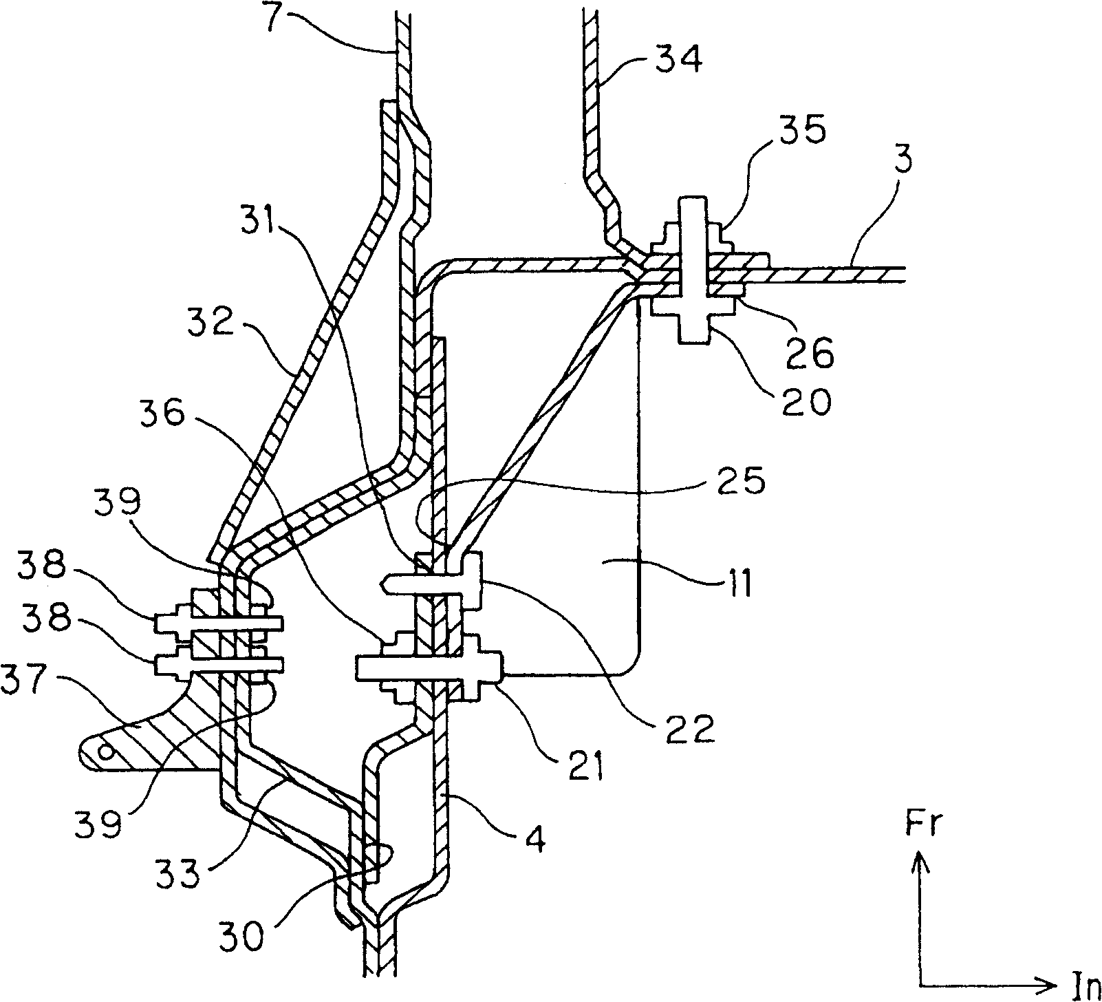
[0033] Below, refer to the attached Figures 1 to 5 One embodiment of the connecting structure near the front pillar of the vehicle body according to the present invention will be described. figure 1 It is a schematic diagram showing the connection structure near the front pillar of the vehicle body according to an embodiment of the present invention, figure 2 To show a perspective view of a support bracket according to an embodiment of the present invention, image 3 A sectional view showing a section A-A of a support bracket according to an embodiment of the present invention, Figure 4 To show a sectional view of a support bracket B-B section according to an embodiment of the present invention, Figure 5 It is a perspective view showing a bracket of a deck beam according to an embodiment of the present invention. In the figure, Fr indicates the vehicle front direction, In indicates the vehicle interior side in the vehicle width direction, and Up indicates the vehicle up...


PUM


Abstract

The invention discloses a connecting structure around a vehicle body front pillar capable of reinforcing body rigidity and bracket rigidity. A cowl top inner panel 3 is connected between side panels 7 of lower parts of left and right front pillars 2. The side panel 7 and the front pillar inner panel 4 are connected so that a closed sectional surface may be formed together with the side panel 7 at the cabin inside of the side panel 7. A support bracket 11 for supporting a deck cross member 1 is connected so that a closed sectional surface may be formed together with the cowl top inner panel 3 and the front pillar inner panel 4 to stretch over the cowl top inner panel 3 and the front pillar inner panel 4.

Description

technical field [0001] The invention relates to a connection structure near a front pillar of a vehicle body. Background technique [0002] A steering wheel is arranged in front of the driver's seat of the car to change the driving direction of the vehicle to a desired direction. The steering column supporting the steering wheel is supported at its front by a steering gear on the engine room side, and at its rear by a deck crossmember. In addition, an instrument panel supported by a vehicle body frame member is disposed at the front of the cabin, and a deck beam is located at a lower portion of the instrument panel and also supports the instrument panel. Both ends of the deck beam are connected to the lower parts of the front pillars on the left and right sides of the vehicle body frame members located in the front part of the vehicle compartment. Furthermore, a cowl top is provided in the vehicle width direction in front of the cowl top, so that the front portion of the v...

Claims


Application Information

Patent Timeline
Patent Type & Authority Patents(China)
IPC IPC(8): B62D25/14
Inventor 伊藤良之岛村昌志
Owner MITSUBISHI MOTORS CORP
Features
  • R&D
  • Intellectual Property
  • Life Sciences
  • Materials
  • Tech Scout
  • Unparalleled Data Quality
  • Higher Quality Content
  • 60% Fewer Hallucinations
Learn More