Supercharge Your Innovation With Domain-Expert AI Agents!

Coating tool and coating appts.

A coating and tool technology, applied in the field of coating tools and coating devices, can solve the problems of difficult and precise fine adjustment and long working time.

Active Publication Date: 2008-10-15
MITSUBISHI MATERIALS CORP
View PDF5 Cites 0 Cited by
  • Summary
  • Abstract
  • Description
  • Claims
  • Application Information

AI Technical Summary

Problems solved by technology

Therefore, the pushing state of the head member obtained by a plurality of push rods interferes with each other, and a non-contact portion is likely to occur between the front end of the push rod and the front end of the head member. Adjusting the width to the desired value caused the problem that the operation time became longer
[0011] In addition, since the width of the slot is adjusted by directly pressing the front end of the head member by screwing in the adjustment bolt, the amount of adjustment of the width of the slot (action of changing the width of the slot) depends on the positive position of the adjustment bolt. The pitch of the thread teeth cut out on the threaded part is difficult to perform fine adjustments such as precision grades

Method used


Image

  • Coating tool and coating appts.
  • Coating tool and coating appts.
  • Coating tool and coating appts.

Examples


Embodiment Construction

[0026] Hereinafter, embodiments of the present invention will be described with reference to the drawings.

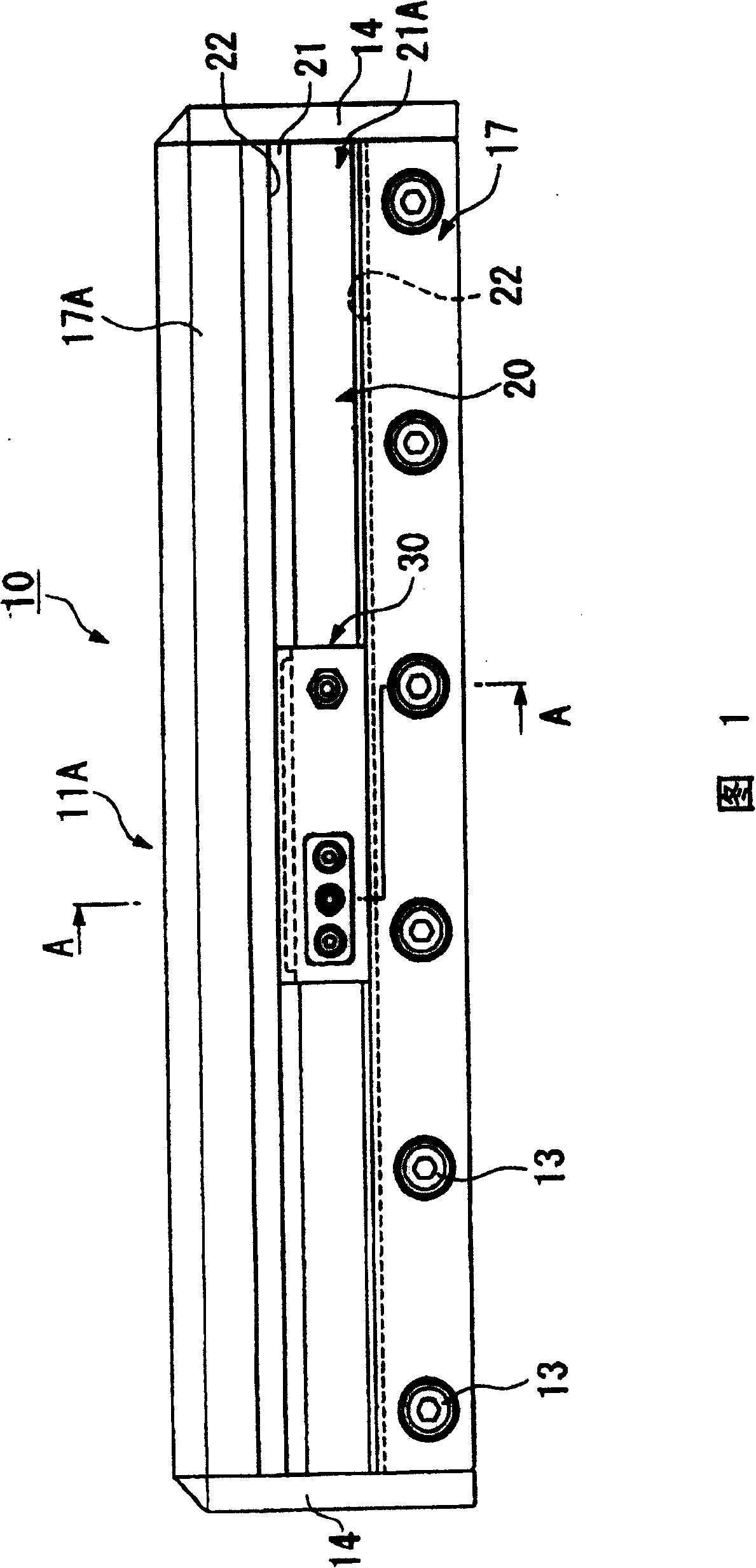
[0027] Figure 1 and figure 2 As shown, the coating head 10 of the coating tool according to the first embodiment of the present invention is composed of a pair of head parts 11A, 11B such that their one side surfaces 12, 12 are opposed to each other, thus forming a vertically long shape. .

[0028] In addition, the pair of head members 11A, 11B constituting the coating head 10 pass through their mutual rear end sides (FIGS. 1 and 10). figure 2 The part on the lower side) is fixed by a plurality of bolts 13 at predetermined intervals in the direction along the length direction of the coating head 10 (the left-right direction in FIG. 1 ), and is positioned relative to the Side plates 14, 14 are attached to the end faces of both ends in the direction of the longitudinal direction, respectively, so as to be fixed to each other.

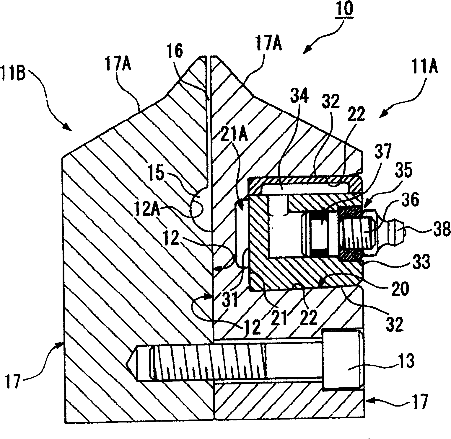
[0029] One head part 11A ( figure 2 Amon...


PUM


Abstract

A coating tool and a coating apparatus using the coating tool are provided, to allow the width of a slot to be controlled easily without repeated control operations. The coating tool has a coating head(10) comprising a plurality of head members(11A, 11B), and a groove-type slot(16) which is open at the terminal of the coating heads and is divided between the sides(12) facing each other at the head members, wherein a coating solution passes through the slot so as to be discharged from the terminal of the coating heads. A concave part(20) of a pair of wall parts facing each other toward the direction along the elongation direction of the slot which is a circulation direction of the coating solution, is formed at the opposite side(17) of the side where the slot forms divisions at the head members. A control unit is installed in the concave part, and it enlarges the length at the direction along the elongation direction of the slot to modify the head member so as to increase the distance between the pair of walls, thereby controlling the width of the slot.

Description

technical field [0001] The present invention relates to a coating device for coating a coating liquid on an object to be coated, and a coating tool mounted on the coating device. Background technique [0002] In the prior art, as a coating tool, some are known: for example, there is a coating head composed of a pair of head parts, and there are: supply coating between the sides of the pair of head parts facing each other. A pocket of liquid; a groove-shaped slot extending from the pocket to the front end side and opening at the front end of the coating head. [0003] In such a coating tool, the front end of the coating head is arranged to face the object to be coated, and the longitudinal direction of the coating head (the longitudinal direction of the slot) is installed on the coating surface so that the longitudinal direction of the coating head (the longitudinal direction of the slot) coincides with the width direction of the object to be coated. On the device, the coati...

Claims


Application Information

Patent Timeline
Patent Type & Authority Patents(China)
IPC IPC(8): B05C5/02B05C9/06
CPCA61H33/028A61H33/065A61H33/066A61H33/6068A61H2033/068A61H2201/0149A61H2201/02A61H2203/0431
Inventor 安竹睦美高桥和彦挂桥典之金山利彦福田努
Owner MITSUBISHI MATERIALS CORP
Features
  • R&D
  • Intellectual Property
  • Life Sciences
  • Materials
  • Tech Scout
  • Unparalleled Data Quality
  • Higher Quality Content
  • 60% Fewer Hallucinations
Learn More