Buckling mechanism and notebook computer therewith

A notebook computer and buckle lock technology, applied in the direction of electrical digital data processing, instruments, digital data processing parts, etc., can solve the problems of poor lubricity of anti-plating solution, increased friction force of latch parts 122, uneven film thickness, etc., to achieve The effect of increasing elasticity

Active Publication Date: 2008-10-15
ASUSTEK COMPUTER INC
View PDF6 Cites 0 Cited by
  • Summary
  • Abstract
  • Description
  • Claims
  • Application Information

AI Technical Summary

Problems solved by technology

[0015] However, this design not only limits the materials that can be selected for the latch member 122, but also causes many disadvantages due to the aforementioned anti-plating solution.
For example, due to the poor lubricity of the anti-plating solution itself, when it adheres to the sliding part 1221, it will increase the friction force of the latch 122 when sliding
Furthermore, it is difficult to control the film thickness of the anti-plating solution adhering to the sliding part 1221. In addition to increasing the thickness of the latch 122, there may also be uneven film thickness.
All of the above shortcomings will affect the smoothness of the latch 122 when sliding.

Method used


Image

  • Buckling mechanism and notebook computer therewith
  • Buckling mechanism and notebook computer therewith
  • Buckling mechanism and notebook computer therewith

Examples


Embodiment Construction

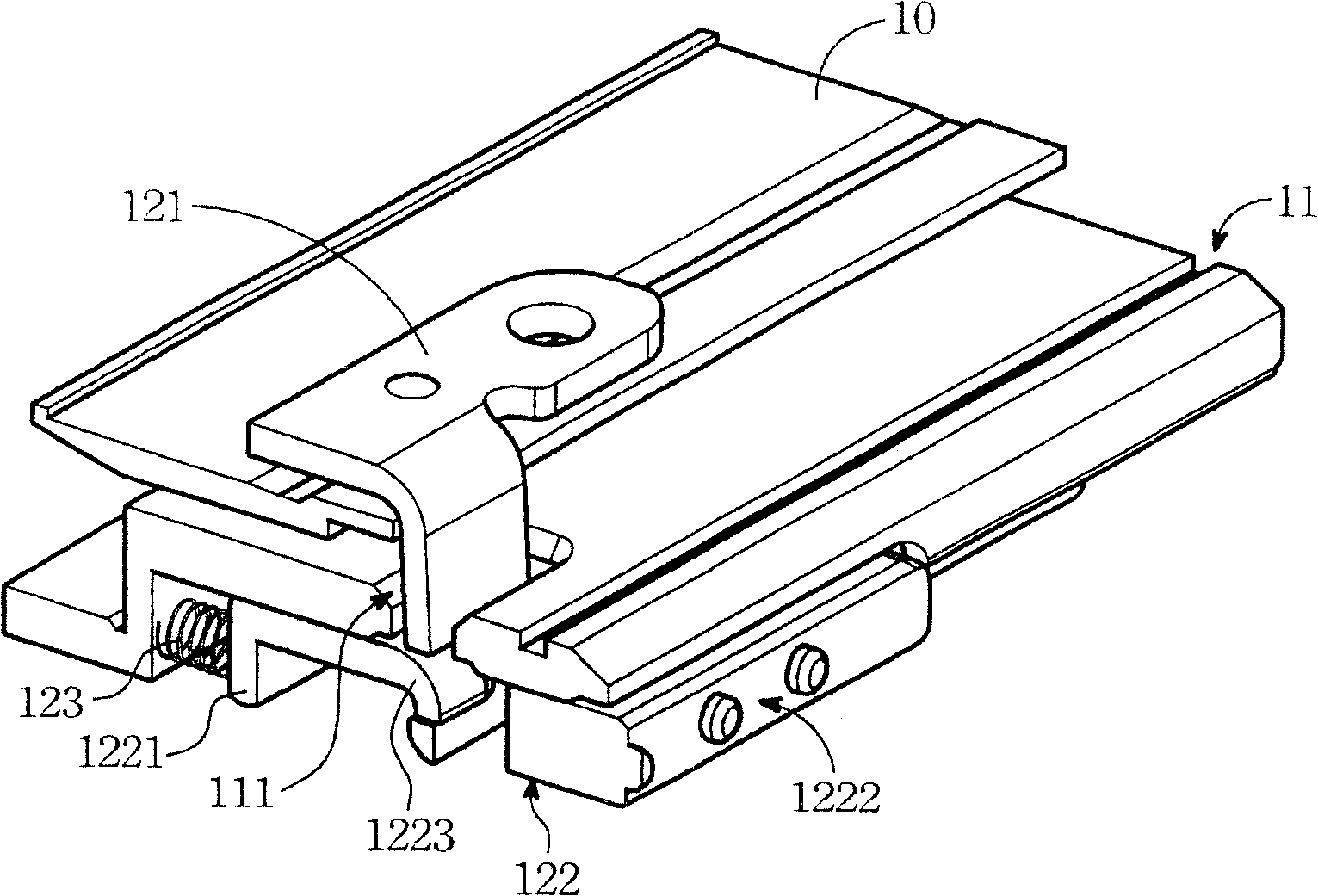
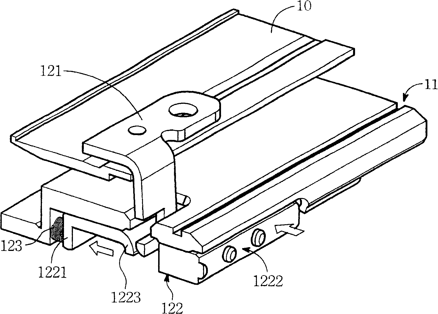
[0031] See Figure 4 , Which is an embodiment of the buckle lock mechanism of the present invention. As shown in the figure, the buckle lock mechanism 2 includes a first lock member 21, a sliding plate 22, and a button 23.

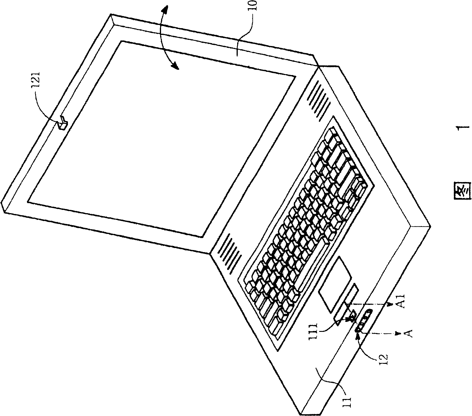
[0032] When assembling, the first locking member 21 and the sliding plate 22 are respectively arranged in two parts that are pivotally connected to each other and are to be fastened together. For example, when the latch mechanism 2 of the present invention is used in a clamshell device, if the first latch is provided on the upper cover of the clamshell device, the sliding plate is set on the base of the clamshell device , The sliding plate 22 is opposite to the first locking member 21 up and down. In addition, the sliding plate has a second locking member 221, which can be buckled with the first locking member 21, so that the upper cover can be fixed on the base. Of course, in other embodiments, the first locking member can also be arranged on the base of the ...


PUM


Abstract

A locking mechanism of notebook computer is prepared as setting slide disc and the first locking element separately on top cover and on base, arranging the second locking element on slide disc for using it to lock the first locking element with each other so as to fix top cover on base, setting key on slide disc and enabling to push slide disc to move for making the second locking element be released from the first locking element so as to lift top cover up by pressing said key.

Description

Technical field [0001] The invention relates to a buckle lock mechanism, in particular to a buckle lock mechanism suitable for notebook computers. Background technique [0002] Please refer to Figure 1, which is a schematic diagram of a notebook computer. As shown in the figure, the notebook computer is mainly composed of a display panel 10 and a host base 11. The main base 11 is provided with various electronic components such as a processor, a memory, and an interface card, and the display panel 10 is pivotally connected to the side of the main base 11 and can be opened and closed up and down. [0003] Among them, when the notebook computer is not in use, for the convenience of carrying, the display panel 10 is covered on the main base 11 and fixed by a buckle mechanism 12, until the buckle mechanism 12 is used to release the display panel 10 , And the display panel 10 can be lifted from the host base 11. [0004] The main components of the locking mechanism 12 are arranged in ...

Claims


Application Information

Patent Timeline
Patent Type & Authority Patents(China)
IPC IPC(8): G06F1/16
Inventor 林山峯吉智勇
Owner ASUSTEK COMPUTER INC
Why Eureka
Try Eureka