Synthetic RF detection system and method
A technology for detectors and radio frequency signals, applied in the field of synthetic radio frequency detection systems and methods, capable of solving problems such as insufficient testing/detection
- Summary
- Abstract
- Description
- Claims
- Application Information
AI Technical Summary
Problems solved by technology
Method used
Image
Examples
no. 1 example
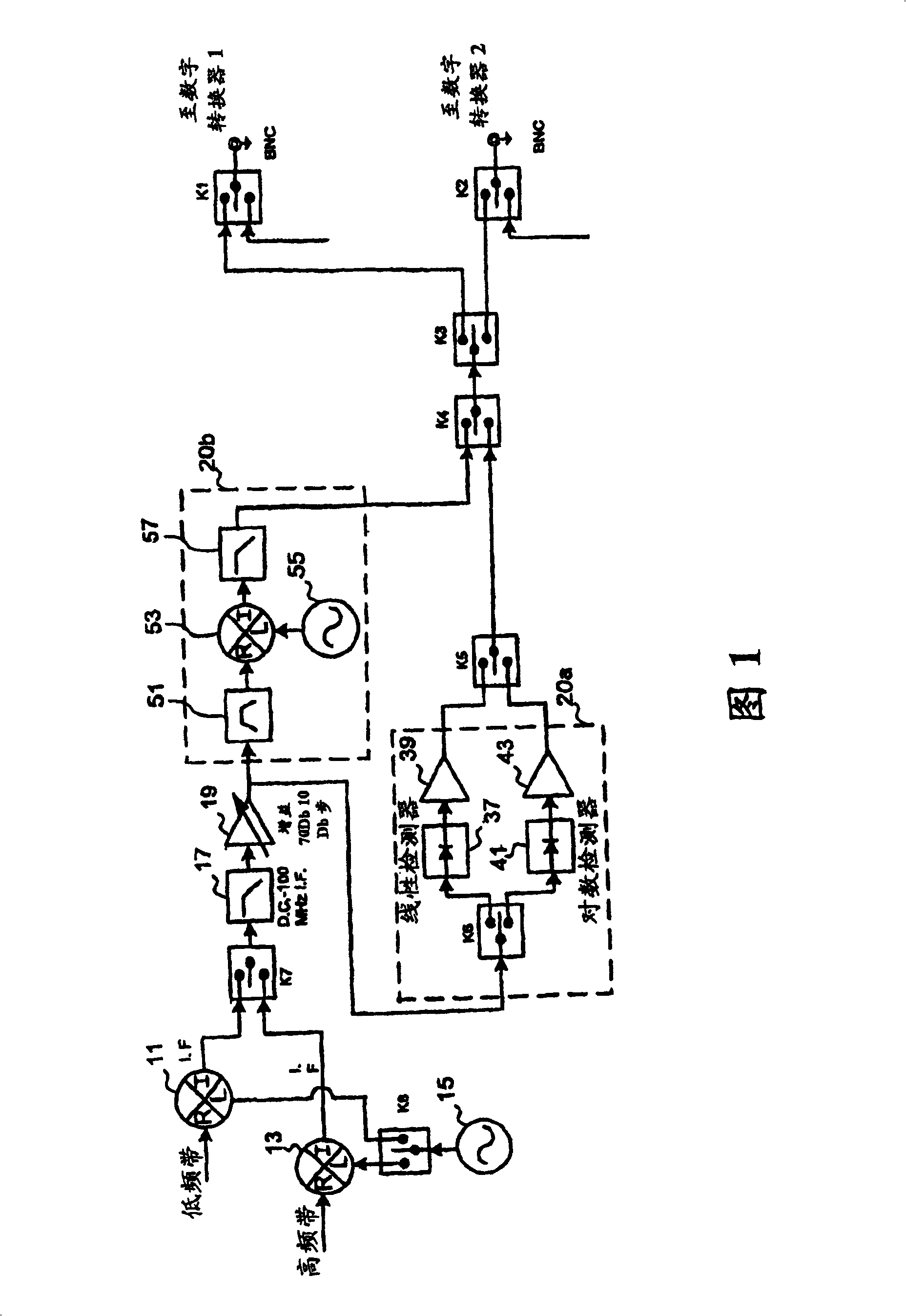
[0018] FIG. 1 illustrates a hardware configuration according to a first embodiment 1 of the present invention. As shown, the mixers 11 and 13 receive low-band and high-band signals from one signal input connector (not shown). A source 15 (eg local oscillator) also feeds the mixer via routing relay K8, which may also be a power divider. The resulting IF signal output from mixer 11 or 13 is applied to routing relay K7, and after passing through additional circuitry via routing relay K1 or K2, K7 preferably multiplexes each output IF signal one at a time into a single digital converter (not shown), as described below.
[0019] After passing through the routing relay K7, the selected signal passes through a low-pass filter 17 and a high-gain amplifier 19 . The output of high gain amplifier 19 is split such that the signal passes through two different sets of circuit components (indicated by dashed boxes 20a and 20b). In the first group of components 20a, the relay K6 applies a ...
no. 2 example
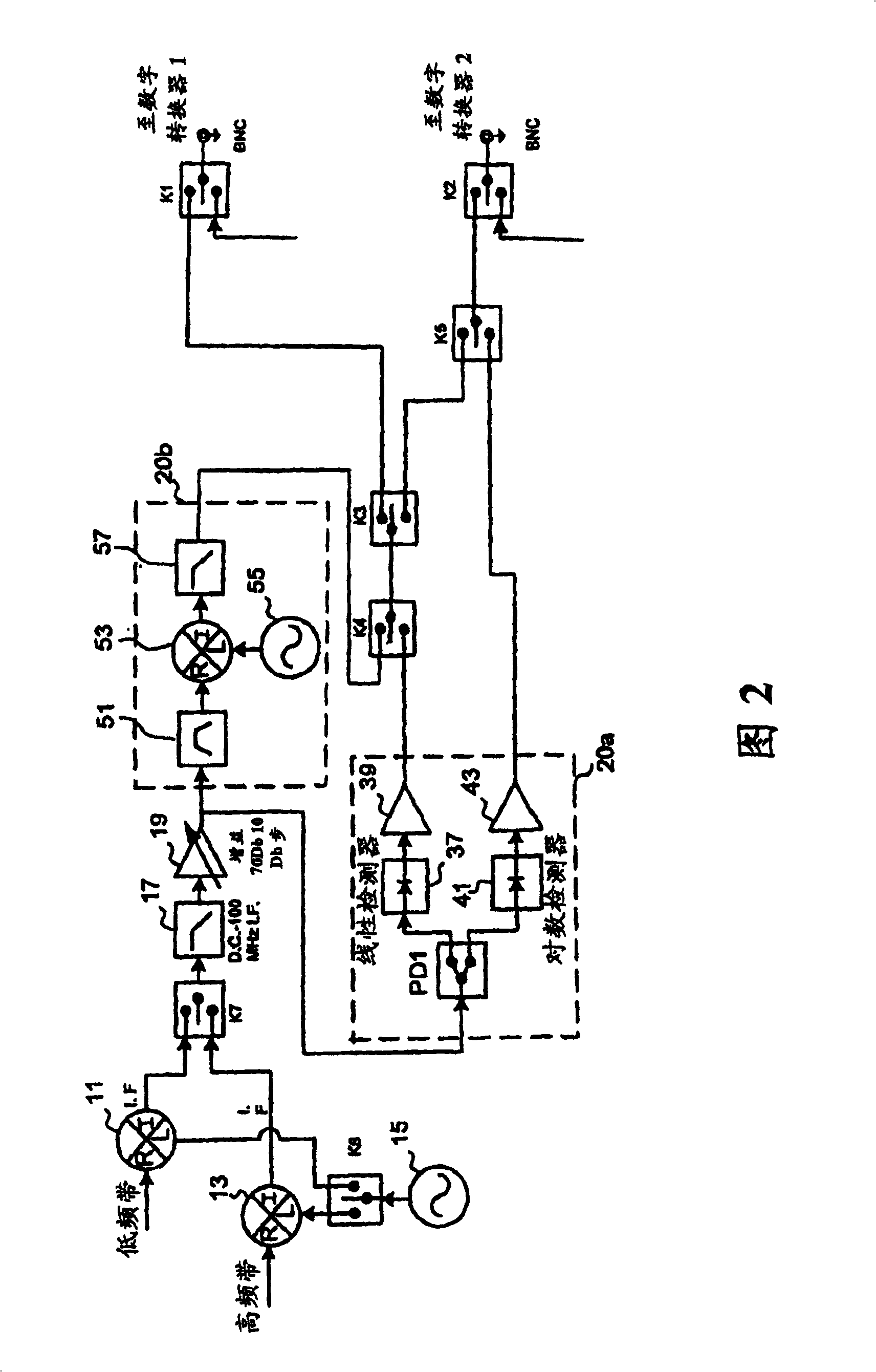
[0024] The configuration of the equipment in the second embodiment 2 is slightly different from that of the first embodiment, the difference is that, as shown in Figure 2, the routing relay K5 is placed between the routing relays K2 and K3. According to this second embodiment, it is possible to simultaneously feed the outputs of detectors 37 and 41 to the inputs of separate digitizers connected to routing relays K1 and K2.
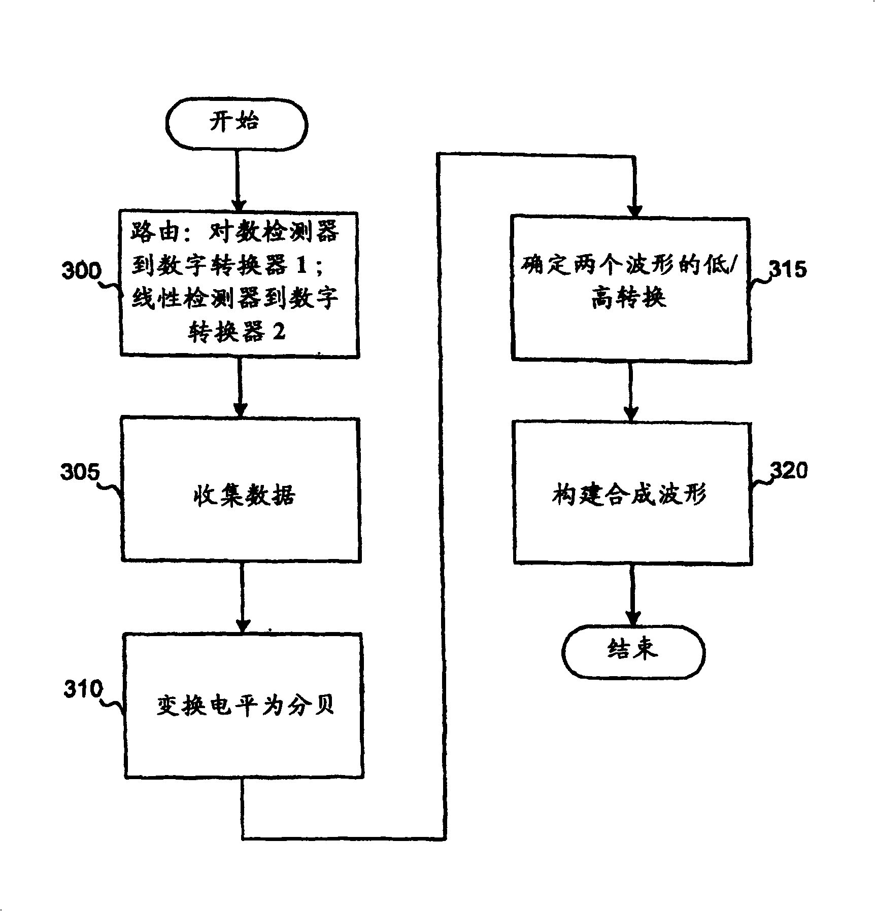
[0025] image 3 Shown are exemplary steps of a software algorithm or a hardware-implemented process for implementing a synthesized RF detector by constructing a synthesized waveform in accordance with the present invention. In the first embodiment of the present invention, the process described below is performed after the data from the linear detector 37 and the logarithmic detector 41 are digitized by the digitizer and recorded or stored. In the second embodiment, since both detectors can be simultaneously monitored by independent digitizers, the collect...
PUM
 Abstract
Description
Claims
Application Information
 - R&D
- Intellectual Property
- Life Sciences
- Materials
- Tech Scout
- Unparalleled Data Quality
- Higher Quality Content
- 60% Fewer Hallucinations
Browse by: Latest US Patents, China's latest patents, Technical Efficacy Thesaurus, Application Domain, Technology Topic, Popular Technical Reports.
© 2025 PatSnap. All rights reserved.Legal|Privacy policy|Modern Slavery Act Transparency Statement|Sitemap|About US| Contact US: help@patsnap.com


