Single-sheet conveying printing machine
A printing machine and sheet-fed technology, applied to printing machines, rotary printing machines, screen printing machines, etc., can solve problems such as troublesome, time-consuming replacement operations, etc.
- Summary
- Abstract
- Description
- Claims
- Application Information
AI Technical Summary
Problems solved by technology
Method used
Image
Examples
no. 1 example
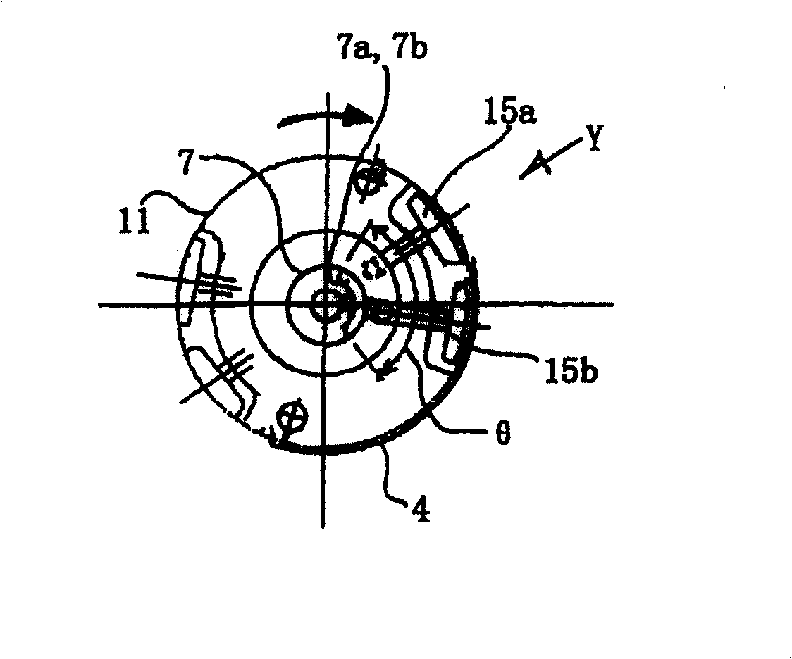
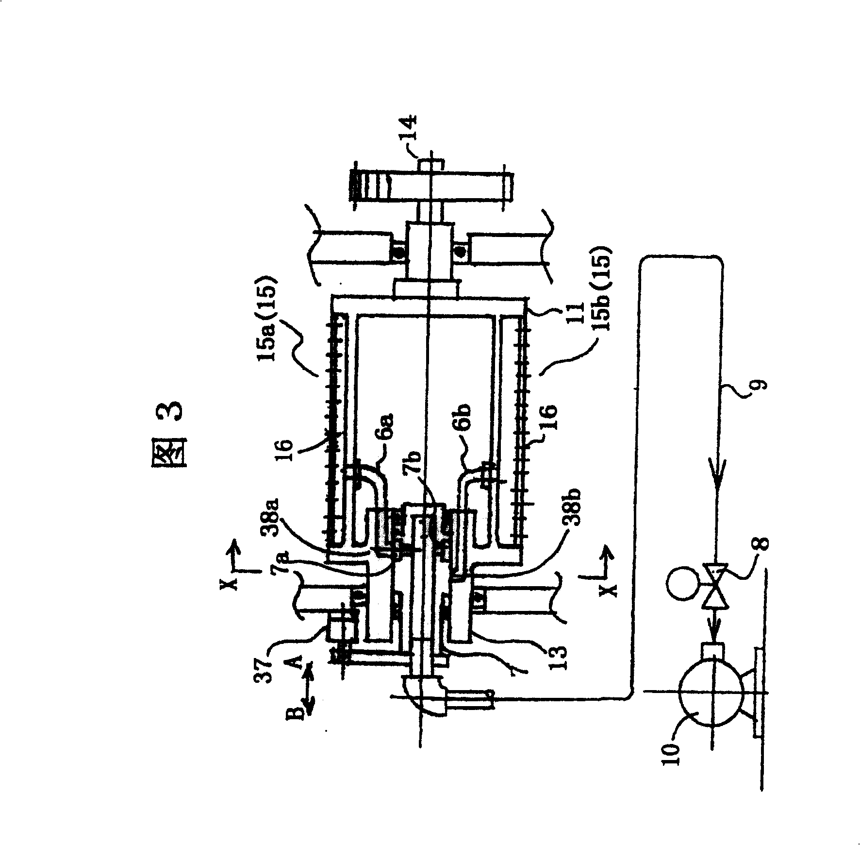
[0036] Figure 2~4 A sheet-fed transfer printing press according to a first embodiment of the present invention is shown.
[0037] figure 2 is a cross-sectional view of the structure of the intermediate cylinder (suction cylinder) used in the sheet-fed transfer printing machine of the first embodiment. Fig. 3 is a longitudinal sectional view of the intermediate drum. Figure 4 is an example of the layout of the suction holes formed in the intermediate drum.
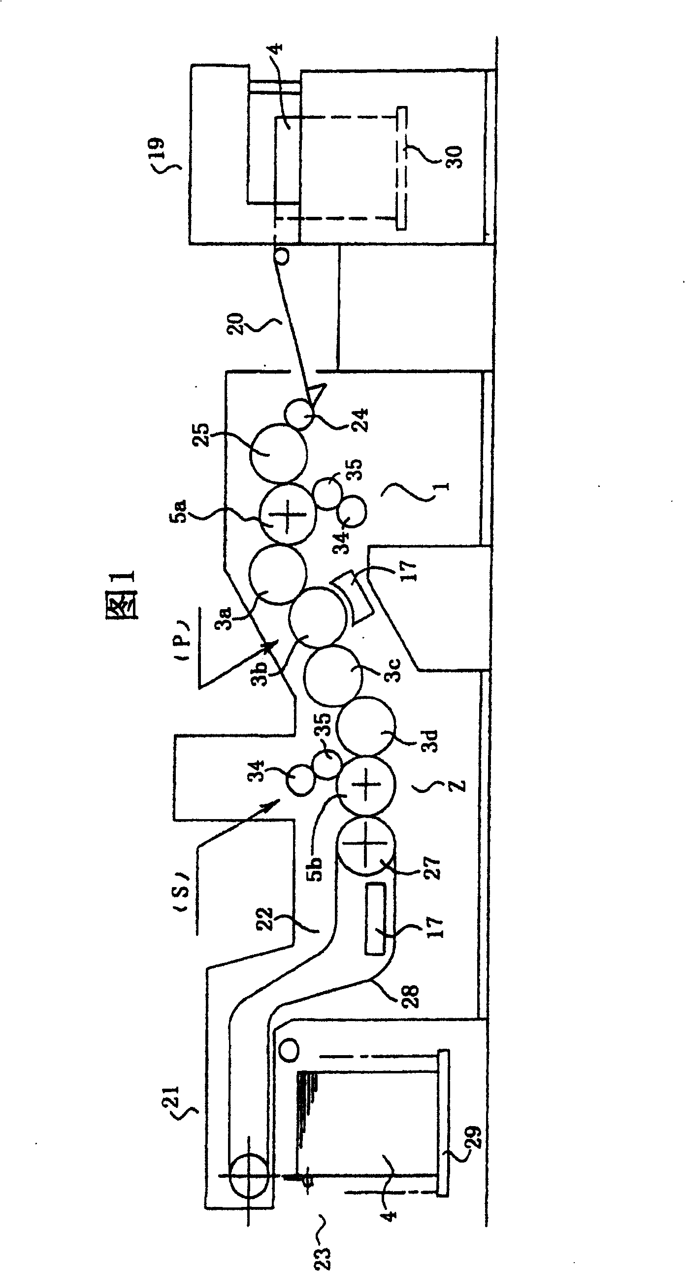
[0038] In the first embodiment, four intermediate cylinders 3a to 3d are installed between the reverse printing sheet 1 and the front printing sheet 2 in Fig. 1, and only the second intermediate cylinder 3b has a suction device arranged on its outer surface mechanism. That is, the second intermediate cylinder 3b is configured to hold the paper on its peripheral surface by suction, thereby conveying the paper smoothly. More specifically, the second intermediate drum 3 b includes a box (main body) 11 , a rotation shaf...
no. 2 example
[0053] Fig. 5 shows a sheet-fed transfer printing machine constructed in accordance with a second embodiment of the present invention. In the second embodiment, two intermediate cylinders (intermediate suction cylinders) are installed in a sheet-fed transfer printing press.
[0054] As shown in FIG. 5 , in a duplex printing machine configured to perform duplex single-color printing on paper 4 , a second intermediate cylinder 3 b and a fourth intermediate cylinder 3 d according to a second embodiment of the present invention are installed in a reverse printing unit 1 Between the printing cylinder 5a of the front printing unit 2 and the printing cylinder 5b of the front printing unit 2. In addition, two dryers 17 are installed close to the second and fourth intermediate drums 3b and 3d, respectively. The basic printing functions are the same as those of a conventional perfecting press.
[0055] In FIG. 5, two dryers 17 are provided, and the two intermediate drums 3b, 3d corres...
no. 3 example
[0058] Figure 6 to Figure 8 A sheet-fed transfer printing machine constructed according to a third embodiment of the present invention is shown.
[0059] 6 is a sectional view of a sheet-fed transfer printing machine of a third embodiment, Figure 7 is a perspective view of the intermediate drum and air jets of the third embodiment, Figure 8 Is a side view of the middle drum used to explain the range of preferred locations for air injection in the air shower.
[0060] In the sheet-fed delivery printing machine of the third embodiment, as shown in Figure 6, the sheet-fed delivery printing machine of the first embodiment is increased as the air shower room 50 of jet device and as imaging device (such as CCD) camera, CMOS or infrared sensor, etc.) image sensor 60.
[0061] The air shower chamber 50 is configured with a plurality of air injection ports 50a facing the second intermediate drum 3b. The second intermediate cylinder 3 b is provided with a dryer 17 intersecting th...
PUM
 Abstract
Description
Claims
Application Information
 - R&D
- Intellectual Property
- Life Sciences
- Materials
- Tech Scout
- Unparalleled Data Quality
- Higher Quality Content
- 60% Fewer Hallucinations
Browse by: Latest US Patents, China's latest patents, Technical Efficacy Thesaurus, Application Domain, Technology Topic, Popular Technical Reports.
© 2025 PatSnap. All rights reserved.Legal|Privacy policy|Modern Slavery Act Transparency Statement|Sitemap|About US| Contact US: help@patsnap.com


