
Plastic forming machine and method for operating same

A molding machine and plastic technology, applied in the field of operating plastic molding machines, can solve the problems of different unloading characteristics of hydraulic pressure accumulators, etc.

Pending Publication Date: 2020-06-23
ENGEL MACHINERY SHANGHAI
View PDF3 Cites 0 Cited by
  • Summary
  • Abstract
  • Description
  • Claims
  • Application Information

AI Technical Summary

Problems solved by technology

However, the fundamental problem cannot be solved in this way: the unloading behavior of the hydraulic pressure accumulator differs significantly from the behavior required for the dynamic pressure curves occurring in practice

Method used


Image

  • Plastic forming machine and method for operating same
  • Plastic forming machine and method for operating same
  • Plastic forming machine and method for operating same

Examples


Embodiment Construction

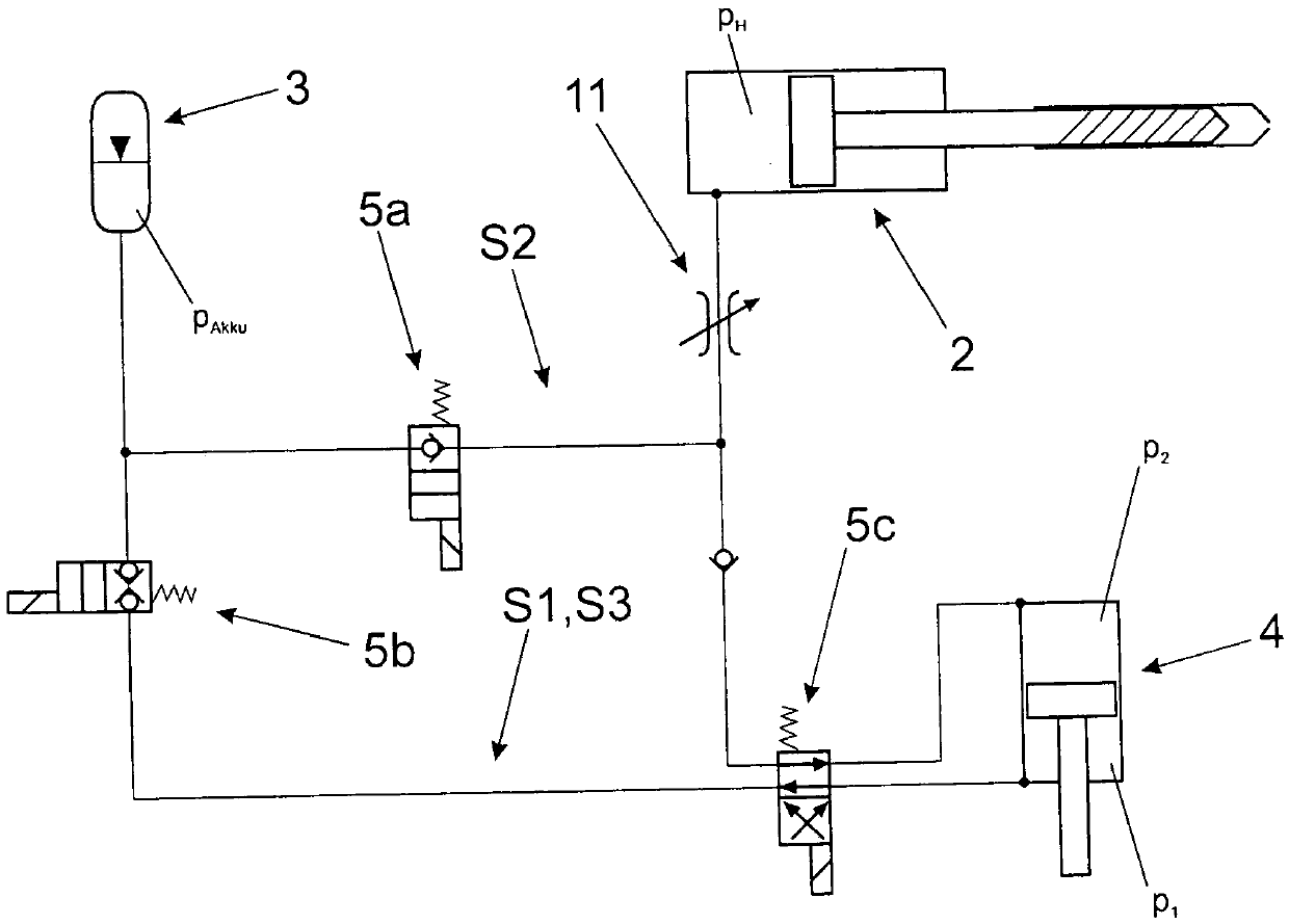
[0039] Figure 1a Firstly, a first exemplary embodiment of a hydraulic circuit for operating a plastics molding machine as an injection cylinder of a consumer 2 is shown. Firstly, the pressure accumulator 3 is shown, which utilizes the accumulated pressure p Akku load. Furthermore, there is a pressure transducer 4 which is implemented via a circuit with a plurality of switching valves 5a, 5b, 5c.

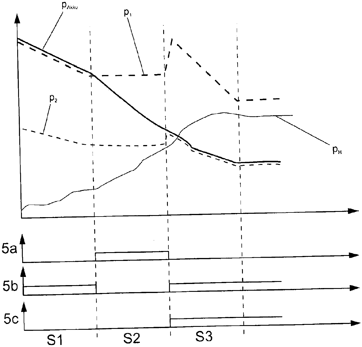
[0040] The consumer 2 is supplied by the line, wherein a volume flow regulating valve 11 is also provided for regulating the process, for example regulating the injection speed. The three stages S1 , S2 , S3 of pressurization and depressurization are realized by said switching valves 5 a , 5 b , 5 c. The first stage S1 is activated when the boost valve 5b is switched on. Therefore, the stored accumulated pressure p at the pressure accumulator 3 Akku The lower hydraulic fluid is led into the lower chamber of the pressure transducer 4 in the figure. In the pressure transducer 4, ...


PUM


Abstract

Disclosed is a plastic forming machine. The plastic forming machine is provided with at least one consuming device (2) capable of being hydraulically operated, at least one hydraulic pressure memory(3), and at least one hydraulic pressure transducer (4) connected between the pressure memory (3) and the at least one consuming device (2). At least two pressure increasing and / or pressure reducingstages (S1, S2 and S3) are realized by using the at least one pressure transducer (4) are available.

Description

technical field [0001] The invention relates to a plastics molding machine with the features stated in the preamble of claim 1 and to a method for operating a plastics molding machine. Background technique [0002] Plastic molding machines are understood here to mean, for example, injection molding machines, injection presses and the like. [0003] A brief overview of the prior art by injection molding machine follows. But similar conclusions and statements apply to plastic molding machines in general. [0004] It is known to use pressure accumulators in hydraulic injection molding machines in order to provide short-term high energy or volume flows, which are possible only with very high additional power by the drive system. [0005] Due to the nature of hydraulic pressure accumulators, when the pressure accumulator is unloaded, initially a relatively high pressure is applied, which then drops relatively strongly, so that only a further relatively low pressure is available...

Claims


Application Information

Patent Timeline
Patent Type & Authority Applications(China)
IPC IPC(8): B29C45/54B29C45/58
CPCB29C45/542B29C45/58
Inventor A·洛纳克尔
Owner ENGEL MACHINERY SHANGHAI
Learn More