
Device for writing or reading different optical recording medium

A technology of optical recording media and equipment, applied to optical recording heads, optical recording/reproduction, magnetic recording, etc., capable of solving problems such as impossibility, large error bandwidth, and fluctuations

Inactive Publication Date: 2005-09-21
DEUTSCHE THOMSON-BRANDT GMBH
View PDF1 Cites 0 Cited by
  • Summary
  • Abstract
  • Description
  • Claims
  • Application Information

AI Technical Summary

Problems solved by technology

Depending on the signal level read out at random, large fluctuations can occur in this case, so a large error bandwidth must be taken into account, that is to say, problems can also arise in this case, in the case of In the case of a wide variety of different types of optical recording media of different thickness and / or number of layers, the signal levels used for identification are so close together that unambiguous identification always requires greater complexity or even becomes impossible
Furthermore, unambiguous identification may become practically impossible due to slight fluctuations in the reflectivity of optical recording media determined by production
[0006] It must therefore be considered disadvantageous for these known devices that, according to the prior art, it is no longer possible to reliably identify the various different types of optical recording medium

Method used


Image

  • Device for writing or reading different optical recording medium
  • Device for writing or reading different optical recording medium
  • Device for writing or reading different optical recording medium

Examples


Embodiment Construction

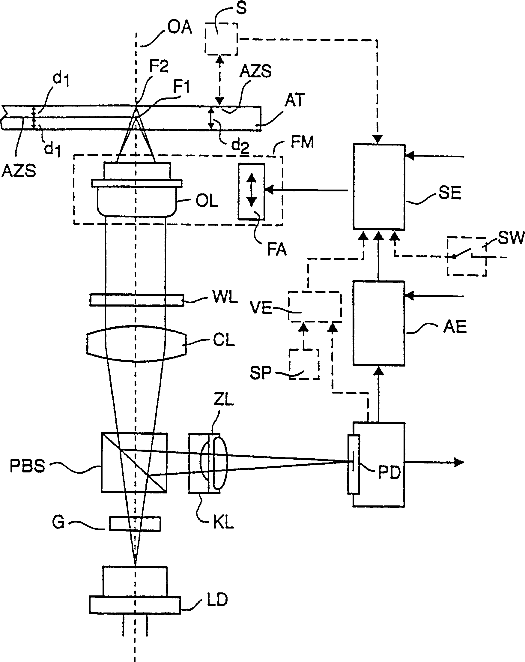
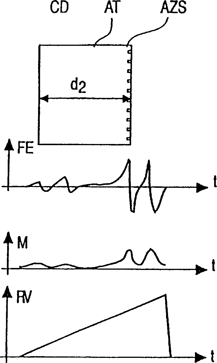
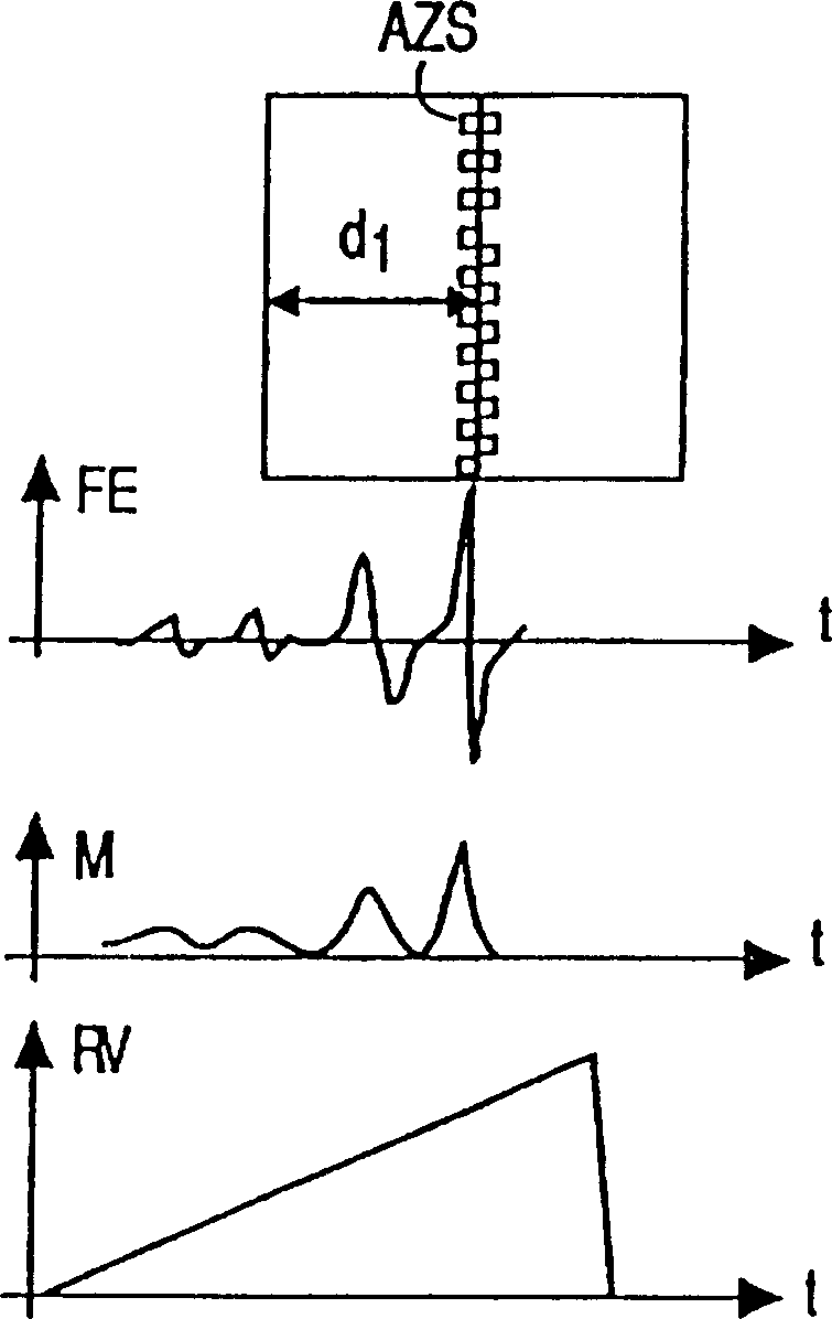
[0026] according to figure 1 The schematic diagram shown is for a reproduction and / or recording device for optical recording media AT with different storage densities, using a scanning device in a reproduction and / or recording device provided for the playback of audio CDs and for the playback of digital video discs. according to figure 1, the scanning device consists of a laser diode LD, a grating G, a polarizing beam splitter PBS, a collimator lens CL, a quarter-wavelength plate WL, an objective lens OL, a concave lens KL, a cylindrical lens ZL and a detector PD. Although digital video discs, hereinafter referred to as DVDs, and audio discs, hereinafter referred to as CDs, have different storage densities, the figure 1 The scanning device shown is likewise used for both types of recording medium AT. The higher storage density of DVD is achieved with a smaller pit size and reduced track pitch compared to CD. In order to reproduce the information stored on the recording medi...


PUM

PropertyMeasurementUnit
reflectanceaaaaaaaaaa

Abstract

The read-write system for optical discs [AT] has a laser diode [LD] output directed through an optical splitter [PBS] and a lens system [CL,WL,OL], and onto the disc. The optical signals are reflected back from tracks on the disc. The nature of the reflected signals will depend upon the depth of the tracks [F1,F2], which are dependent upon the type of recording. The optical signals are reflected through the prism and onto the photo detectors [PD]. A detection unit [AE] indicates an error, and a controller [SE] adjusts the focus to suit the disc. -

Description

[0001] This application is a divisional application of the application number 97192914.9 and the application date of February 27, 1997. technical field [0002] The invention relates to a device for writing to and / or reading from optical recording media having different structures. Background technique [0003] Such devices are disclosed, for example, in EP (European Patent) No. 0 294 490 or "IBM Technical Publication Bulletin, August 1986, Vol. 29, No. 3". In these devices, the type of the optical recording medium is determined using the reflectance of the recording layer. In this case, the intensity of the reflected light is compared with two reference values ​​that make it possible to distinguish (identify) two types of recording media. [0004] In the apparatus disclosed in "IBM Technical Publication, August 1986, Vol. 29, No. 3", the type of an optical recording medium is determined by using the reflectance thereof. In this case, the objective lens of the device moves...

Claims


Application Information

Patent Timeline
Patent Type & Authority Patents(China)
IPC IPC(8): G11B7/00G11B7/004G11B7/085G11B7/09G11B7/135G11B7/1374G11B7/1392G11B19/00G11B19/02G11B19/12
CPCG11B19/00G11B7/1374G11B19/12G11B2019/121G11B2007/0013G11B7/08511G11B2007/0006G11B7/0945G11B7/13922G11B7/1392
Inventor 邓辽金弗里德赫尔姆·朱克海因茨-乔尔格·施罗德
Owner DEUTSCHE THOMSON-BRANDT GMBH
Learn More