

Three-inlet and multi-exit two-stage electromagnetic booster braking general pump
A brake master cylinder, electromagnetic technology, applied in the direction of brake, brake transmission, transportation and packaging, etc., to achieve the effect of accelerating the braking speed, reducing the rebound pressure, and reducing the elasticity
- Summary
- Abstract
- Description
- Claims
- Application Information
AI Technical Summary
Problems solved by technology
Method used
Image

Examples
Embodiment 1
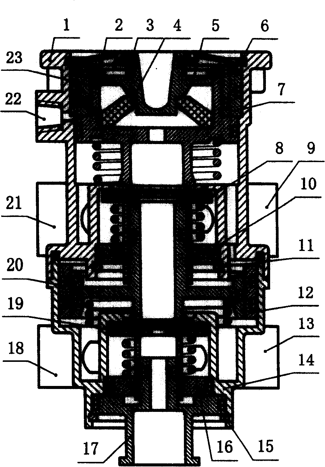
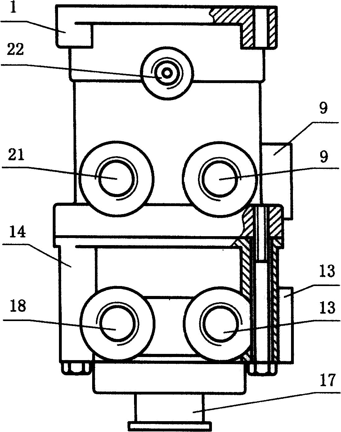
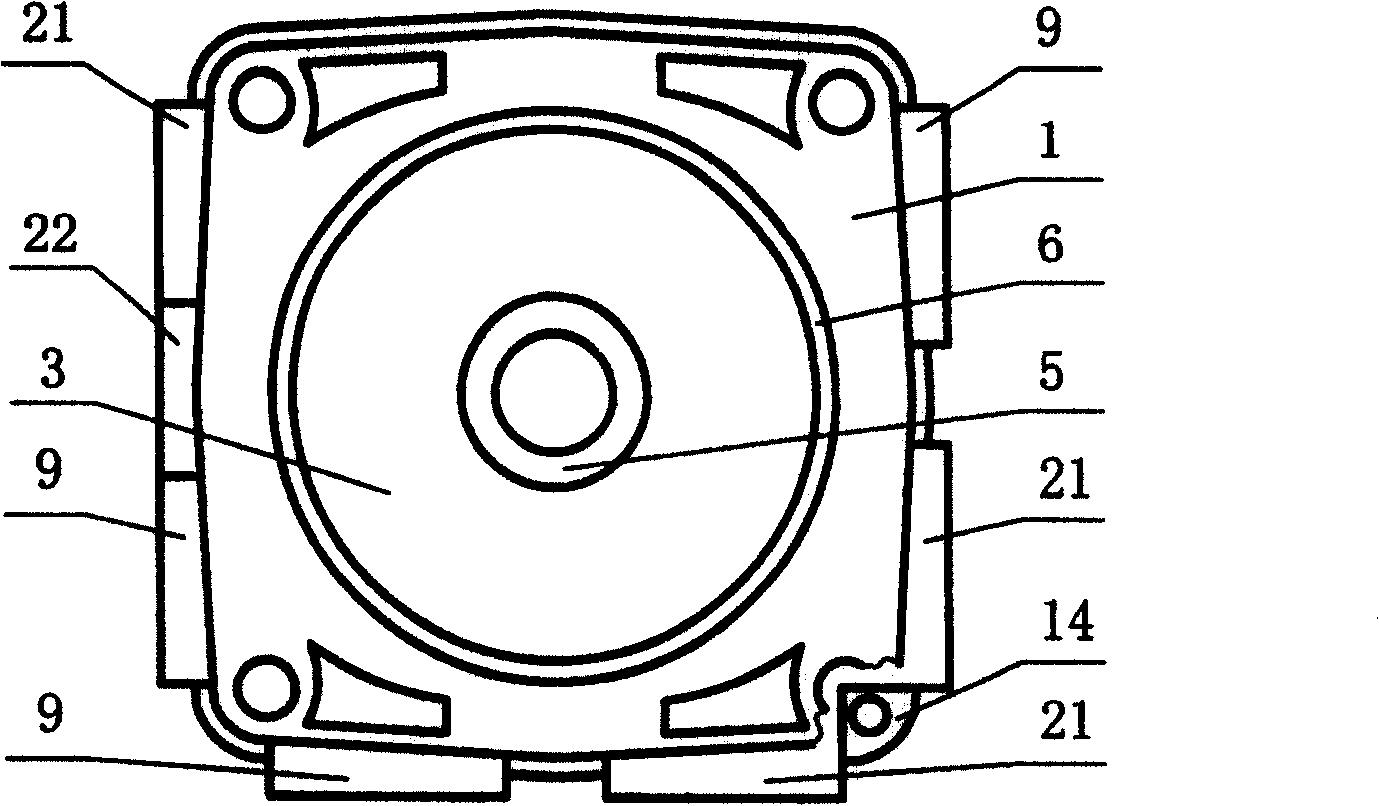
[0025] Embodiment one: see figure 1 , figure 2 , image 3 and Figure 7 , in the figure, 1-upper pump body, 2-retaining spring of ejector seat, 3-dust cover, 4-rubber pad for stabilizing pressure, 5- ejector seat, 6-retaining spring of dust cover, 7-upper piston sleeve , 8-upper valve, 9-rear brake air intake, 10-upper valve plug, 11-upper valve plug retainer, 12-lower piston sleeve, 13-front brake air intake, 14-lower pump Body, 15-lower valve plug circlip, 16-lower valve plug, 17-lower valve plug positioning seat, 18-front brake air outlet, 19-lower valve, 20-lower piston, 21-rear brake Vent, 22-boost air intake, 23-upper piston.
[0026] The three-inlet and multiple-outlet two-stage electromagnetic booster brake master cylinder includes an upper pump body 1 and a lower pump body 14, which are fixedly connected by bolts, and the upper pump body 1 is provided with a push rod seat 5 and a pressure-stabilizing rubber pad 4 , the upper piston 23, the upper return spring, t...
Embodiment 2
[0033] Embodiment two: see Figure 4 , Figure 5 , Figure 6 and Figure 7 , the number in the figure is the same as that of Embodiment 1. The meanings are the same, and the similarities will not be repeated. The difference is: the upper pump body 1, the lower pump body 14, the lower piston 20, the lower piston sleeve 12, and the dust cover 3 The specific structure is different from the corresponding parts in the first embodiment, and the dust cover 3 is provided with a gland 25, although the structures of the corresponding parts are different, but the working principle is the same. This embodiment is suitable for Cummins series air brake type.
PUM
 Abstract
Description
Claims
Application Information