Supercharge Your Innovation With Domain-Expert AI Agents!

Device for hot dip coating metal strands

A metal strip, hot-dip plating technology, applied in the field of metal strips, can solve problems such as strip surface damage, and achieve the effect of improving the adjustability

Inactive Publication Date: 2008-11-26
SMS DEMAG AG
View PDF11 Cites 0 Cited by
  • Summary
  • Abstract
  • Description
  • Claims
  • Application Information

AI Technical Summary

Problems solved by technology

[0009] Coating of non-ferromagnetic metal strips is therefore possible, but with substantially ferromagnetic steel strips, the following problems arise: These strips are drawn ferromagnetically to the channel walls in electromagnetic seals, so that with surface damage
This reinforces the need for an efficient adjustment of the position of the metal strip in the guide channel, which is more difficult by the circumstances described above

Method used


Image

  • Device for hot dip coating metal strands
  • Device for hot dip coating metal strands

Examples


Embodiment Construction

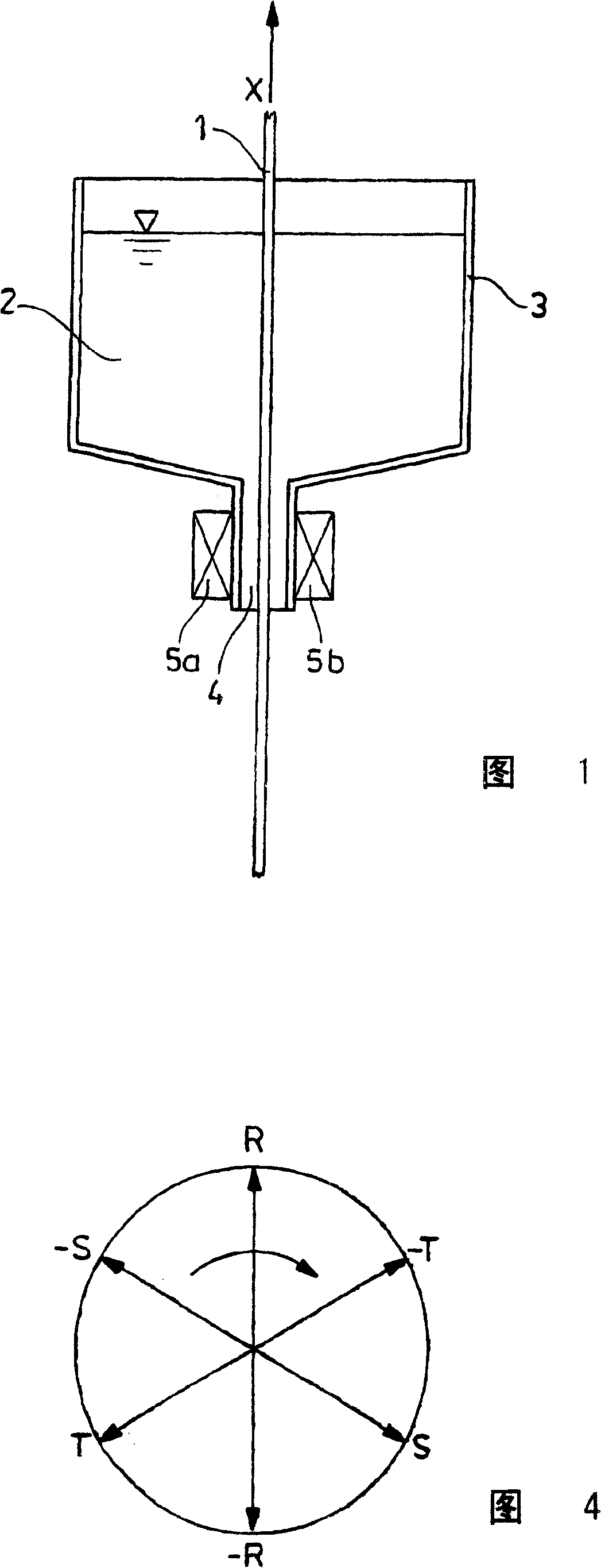
[0030] Figure 1 shows the principle of hot-dip coating a metal strip 1, especially a steel strip. The metal strip 1 to be coated enters the guide channel 4 of the coating device vertically from below. The guide channel 4 forms the lower end of the container 3, which contains the coating metal 2 in the liquid state. The metal strip 1 is guided vertically upward in the movement direction X. In order to prevent the liquid coating metal 2 from flowing out of the container 3, an electromagnetic sensor is arranged in the position of the guide channel 4. The inductor is composed of two halves 5a and 5b, one of which is arranged on each side of the metal strip 1. An electromagnetic moving field is generated in the electromagnetic sensor 5, which resists the liquid coating metal 2 in the blocking container 3 and prevents it from flowing out.

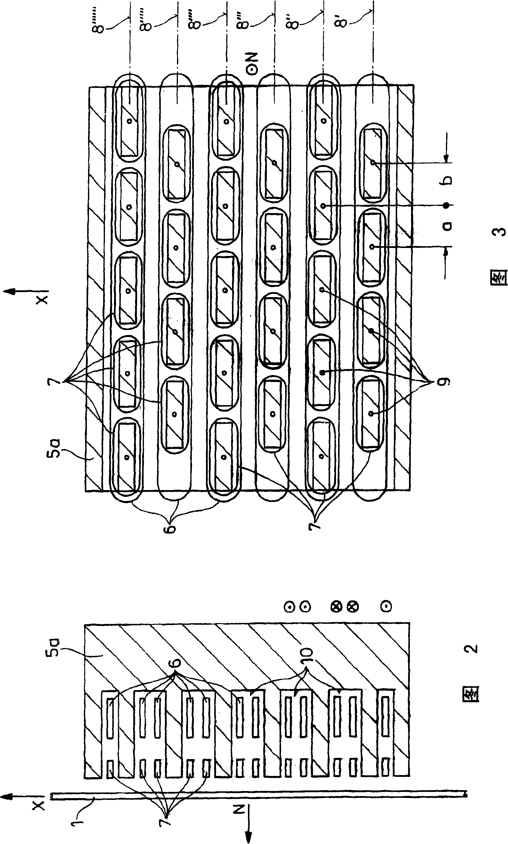
[0031] The exact configuration of the electromagnetic inductor 5 can be seen in FIGS. 2 and 3. What is shown is only one of two symmetrically formed...


PUM


Abstract

The invention relates to a device for hot dip coating metal strands (1), particularly strip steel, in which the metal strand (1) can be vertically guided through a reservoir (3), which accommodates the molten coating metal (2), and though a guide channel (4) connected upstream therefrom. An electromagnetic inductor (5) is mounted in the area of the guide channel (4) and in order to retain the coating metal (2) inside the reservoir (3), can induce induction currents in the coating metal (2) by means of an electromagnetic traveling field. While interacting with the electromagnetic traveling field, said induction currents exert an electromagnetic force. The inductor (5) has at least two main coils (6) that are arranged in succession in movement direction (X) of the metal strand (1), and has at least two correction coils (7) for controlling the position of the metal strand (1) inside the guide channel (4) in direction (N), which is normal to the surface of the metal strand (1). These correction coils are also arranged in succession in movement direction (X) of the metal strand (1). In order to improve the efficiency of the control of the metal strip inside the guide channel, the invention provides that at least a portion of the correction coils (7), when viewed in movement direction (X) of the metal strand (1), are arranged so that they are offset with regard to one another perpendicular to movement direction (X) and perpendicular to direction (N) that is normal to the surface of the metal strand (1).

Description

Technical field [0001] The invention relates to a device for hot-dip coating metal strips, especially steel strips. In this device, the metal strips can vertically pass through a container containing molten coating metal and pass through a front Guide channel. In this case, an electromagnetic sensor is provided in the guide channel, which can induce an induced current in the coated metal by means of an electromagnetic moving field to inhibit the coated metal in the blocking container. The electromagnetic moving field interacts to exert an electromagnetic force, wherein the inductor has at least two main coils, which are arranged in the direction of movement of the metal strip immediately before and after; the inductor also has at least two correction coils, It is used to adjust the position of the metal strip in the guide channel in a direction orthogonal to the surface of the metal strip, and these correction coils are also arranged in the direction of movement of the metal strip...

Claims


Application Information

Patent Timeline
IPC IPC(8): C23C2/24C23C2/40
CPCC23C2/24
Inventor F·贝尔格曼M·茨伦巴赫W·特拉科夫斯基O·N·耶普森H·贝伦斯
Owner SMS DEMAG AG
Features
  • R&D
  • Intellectual Property
  • Life Sciences
  • Materials
  • Tech Scout
  • Unparalleled Data Quality
  • Higher Quality Content
  • 60% Fewer Hallucinations
Learn More