Platform device conveying roller

A platform device and roller technology, applied in loading/unloading, conveyor objects, transportation and packaging, etc., can solve the problems of small transmission force, complex platform structure, inconvenient maintenance, etc., to improve reliability and effectiveness, platform device Simple structure, flexible and convenient correction

Active Publication Date: 2008-12-03
WEIHAI GUANGTAI AIRPORT EQUIP CO LTD
View PDF5 Cites 0 Cited by
  • Summary
  • Abstract
  • Description
  • Claims
  • Application Information

AI Technical Summary

Problems solved by technology

[0004] In order to overcome the small transmission force and low efficiency when the 45° rollers of the transmission rollers of the existing container and pallet lifting transmission platform device are transmitted front and rear, left and right, the rollers and the cargo pallet are supported and driven by a single point, and the wear is relatively large. In order to increase The transmission force needs to increase the number of rollers; the 90° roller has only one degree of freedom. To complete the forward and backward, left and right, and rotational movements of the goods, the roller shafts must be arranged vertically and horizontally. The layout is difficult; the rollers of the rollers and the cargo pallet are supported and driven by a single point, which causes great wear and tear, and it is inconvenient to maintain, and the axial projection of the outer contour of the rollers is difficult to complete continuous technical deficiencies. The purpose of the present invention is to provide a At the same time, there are more than two support and transmission points, the projection of the outer contour of the roller is completely continuous, and the roller shaft frame is a split assembly structure, which is convenient for installation and maintenance, stable transmission, continuous and efficient platform device transmission roller

Method used


Image

  • Platform device conveying roller
  • Platform device conveying roller
  • Platform device conveying roller

Examples


Embodiment 1

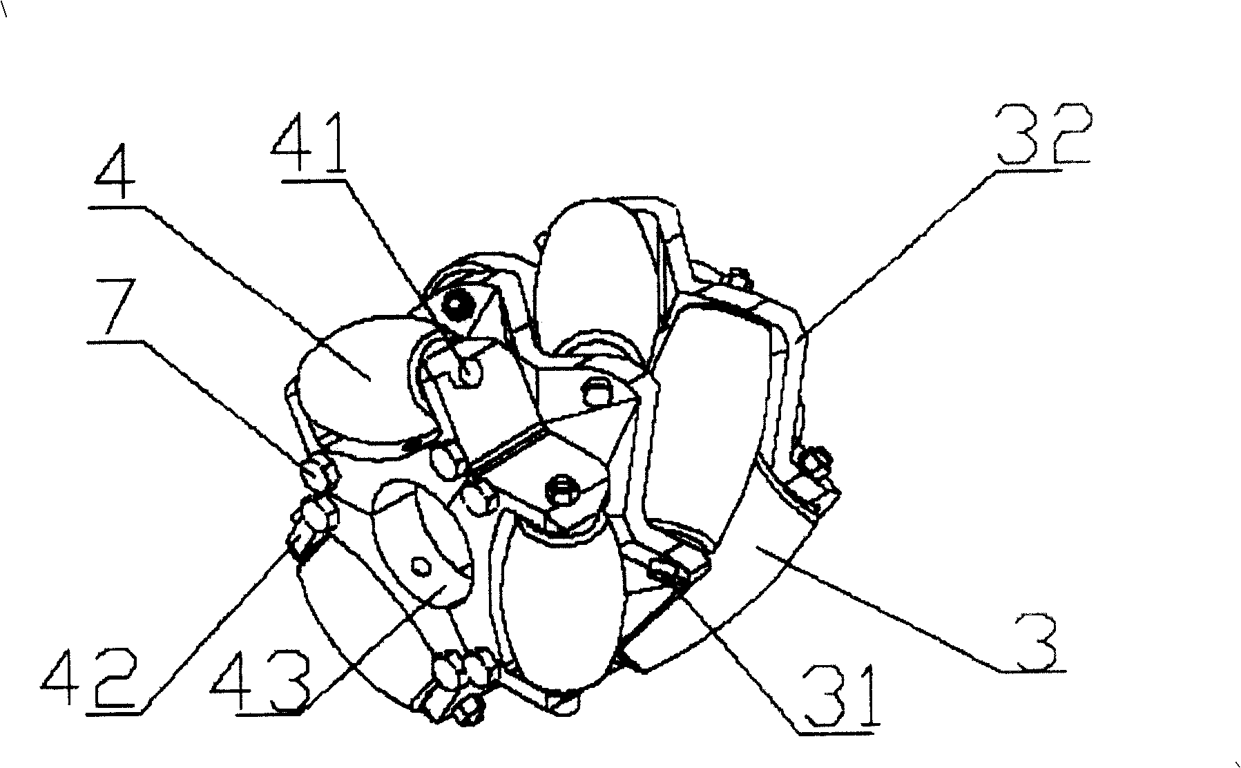
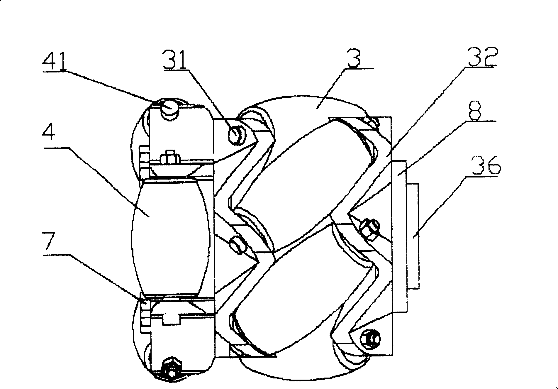
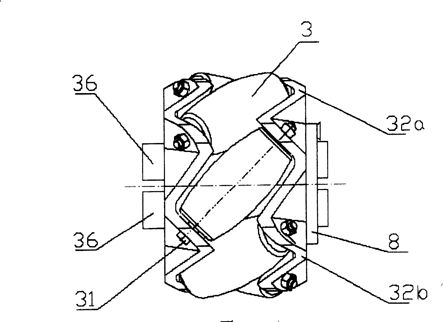
[0024] exist figure 1 , figure 2 , image 3 , Figure 4 , Figure 5 , Figure 6 , among Fig. 7, Fig. 8, the present invention is made up of roller axle frame, roller rotating shaft, roller, and the middle part of roller axle frame is provided with a shaft hole 33, and shaft hole 33 is used for installing main shaft 10, and roller shaft The frame is a rotary assembly composed of split shaft frames. It is composed of 45° roller shaft frame 32 and 90° roller shaft frame 42 arranged side by side. The 45° roller shaft frame 32 is located on the 90° roller shaft frame 42. On the right side, the 45° roller axle frame 32 is a combination of two 45° roller half axle frames 32a and 45° roller half axle frames 32b arranged around the main axis, and the two roller half axle frames 32a, 32b There are fixed bolt holes 35 and key pin holes 34 connected to the main shaft 10 on both ends of the axial direction, and six 45° rollers are evenly installed side by side on the 45° roller brack...

Embodiment 2

[0027]Embodiment 2: The present invention is composed of a roller shaft frame, a roller rotating shaft, and rollers. A shaft hole 33 is provided in the middle of the roller shaft frame. The shaft hole 33 is used to install the main shaft 10, and the roller shaft frame is a split body. The rotary assembly composed of pedestals is composed of 45° roller pedestals 32 and 90° roller pedestals 42 arranged side by side. The 45° roller pedestals 32 are located on the left side of the 90° roller pedestals 42. The roller shaft frame 32 is a combination of two 45° roller half shaft frames 32a and 45° roller half shaft frames 32b arranged around the main axis, and the axial ends of the two roller half shaft frames 32a and 32b There are fixed bolt holes 35 and key pin holes 34 connected with the main shaft 10, and six 45° rollers 3, 45° are evenly installed side by side on the 45° roller shaft frame 32 around the main axis via the 45° roller rotation shaft 31 The angle between the roller ...

Embodiment 3

[0029] The present invention is composed of a roller shaft frame, a roller rotating shaft, and a roller. A shaft hole 33 is provided in the middle of the roller shaft frame. The shaft hole 33 is used to install the main shaft 10. The roller shaft frame is composed of a split shaft frame. The rotary assembly is composed of a 45° roller shaft frame 32 and two 90° roller shaft frames 42 arranged side by side. A 90° roller shaft frame 42 is respectively installed at the left and right ends of the 45° roller shaft frame 32. The 45° roller axle frame 32 is a combination of two 45° roller half axle frames 32a and 45° roller half axle frames 32b arranged around the main axis. The end face is provided with a fixed bolt hole 35 and a key pin hole 34 connected with the main shaft 10. On the 45° roller shaft frame 32, six 45° rollers 3, 45 are evenly installed side by side around the main axis via the 45° roller rotation axis 31. The included angle between the roller rotation axis 31 and ...


PUM


Abstract

The present invention relates to material conveying apparatus comprising parallel 45 deg roller pedestals and 90 deg roller pedestals. The 45 deg roller pedestal is the combination of at least two 45 deg roller semi-pedestals set around the main axis, and 45 deg rollers with rotating shaft in the angle to the main axis of 45 deg are arranged in parallel around the main axis. The 90 deg roller pedestal is the combination of at least three 90 deg single roller pedestals set homogeneously around the main axis, and 90 deg rollers with rotating shaft in the angle to the main axis of 90 deg are located on the 90 deg roller pedestal. There are two bosses set on two ends of the 45 deg roller pedestal, one of the two bosses is fitted to the notch on one end of the 90 deg roller pedestal, and the 45 deg roller pedestal and the 90 deg roller pedestal are screwed into one integral structure.

Description

technical field [0001] The invention relates to the field of cargo transfer and transmission equipment, in particular to a platform device transmission roller of a container and a pallet lifting and transmission platform vehicle. Background technique [0002] As everyone knows, the transmission rollers of the existing containers and pallet lifting transmission platform vehicles can be divided into: 45° roller rollers and 90° roller rollers according to the position of the rollers and the main shaft, and the structure of the roller frame; U.S. Patent US6409010 discloses A kind of 45° roller roller and its combination have been disclosed. U.S. Patents US6340083 and US6315109 respectively disclose a 90° roller roller and its combination; the roller axis of the 45° roller roller is 45° to the main axis of the roller, and its characteristics are: The resultant force of the rollers is consistent with the rotation direction of the goods, which can realize the three operation modes ...

Claims


Application Information

Patent Timeline
Patent Type & Authority Patents(China)
IPC IPC(8): B65G47/53B65G47/00B65G69/22B65G13/10B65G39/12
Inventor 李光太郝绍银徐一多孟岩
Owner WEIHAI GUANGTAI AIRPORT EQUIP CO LTD
Why Eureka
Try Eureka