
Structure of container for reducing agent

A reducing agent and container technology, which is applied in the structural field of reducing agent containers, can solve the problems of inability to detect the remaining amount and concentration of the liquid reducing agent, the supply of reduction catalysts, and the frozen liquid reducing agent taking a certain time to thaw, so as to shorten the thawing time. effect of time

Active Publication Date: 2008-12-03
NISSAN DIESEL MOTOR CO
View PDF5 Cites 0 Cited by
  • Summary
  • Abstract
  • Description
  • Claims
  • Application Information

AI Technical Summary

Problems solved by technology

At the bottom of the reductant container, there are detection parts of a water level gauge and a concentration meter for detecting the remaining amount and concentration of the liquid reductant, and a suction port for the liquid reductant, so as long as the liquid reductant freezes slightly There is a possibility that not only the remaining amount and concentration of the liquid reducing agent cannot be detected, but also the liquid reducing agent cannot be supplied to the reduction catalyst.
For this reason, a heat exchanger is installed on the reducing agent container to circulate the engine cooling water and exchange heat with the liquid reducing agent. The thawing of the liquid reducing agent takes a certain amount of time

Method used


Image

  • Structure of container for reducing agent
  • Structure of container for reducing agent
  • Structure of container for reducing agent

Examples


Embodiment Construction

[0018] The present invention will be described in detail below with reference to the accompanying drawings.

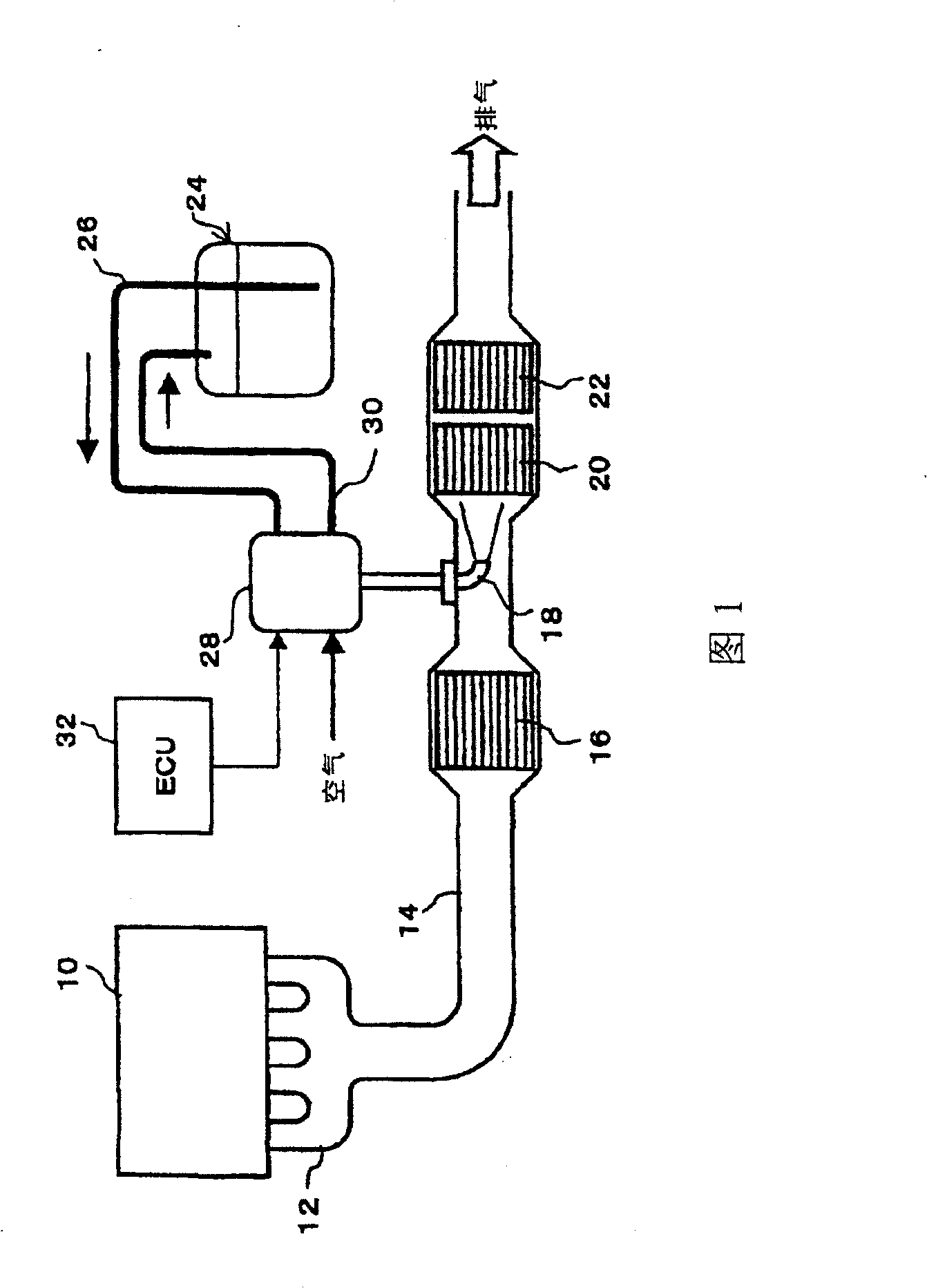
[0019] FIG. 1 shows the overall configuration of an exhaust purification system that uses a urea aqueous solution as a liquid reducing agent to purify NOx contained in engine exhaust by a reduction catalytic reaction.

[0020] On the exhaust pipe 14 connected to the exhaust manifold 12 of the engine 10, there are respectively arranged along the exhaust flow direction: carbon monoxide (NO) is oxidized into nitrogen dioxide (NO 2 ) oxidation catalyst 16; nozzle 18 for spraying and supplying urea aqueous solution; NOx reduction catalyst 20 for reducing and purifying NOx by using ammonia gas obtained by hydrolysis of urea aqueous solution; Catalyst 22. In addition, the urea aqueous solution stored in the reducing agent container 24 is supplied to the reducing agent supply device 28 through the supply pipe 26 whose suction port is located at the bottom of the reducing agen...


PUM


Abstract

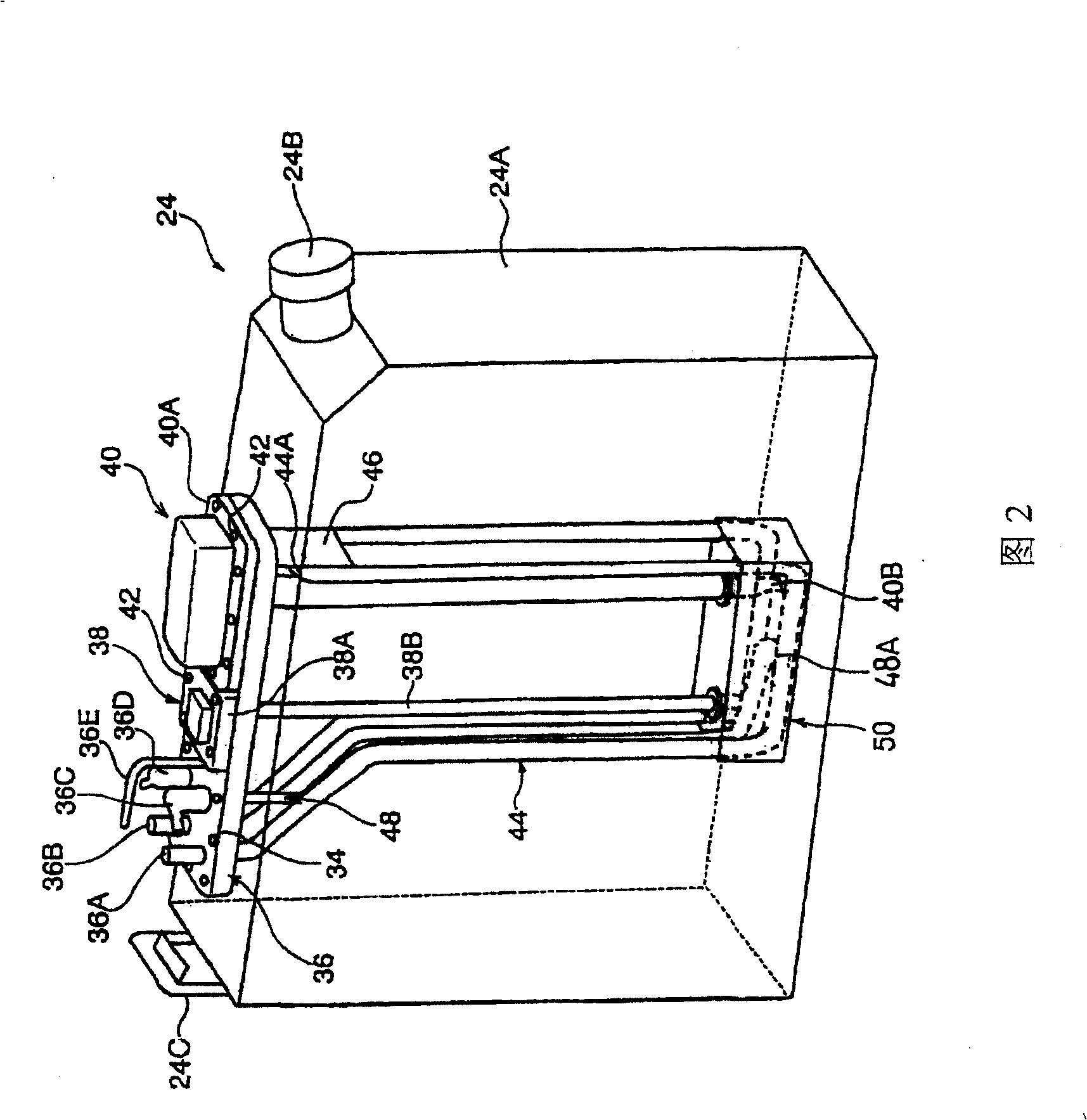
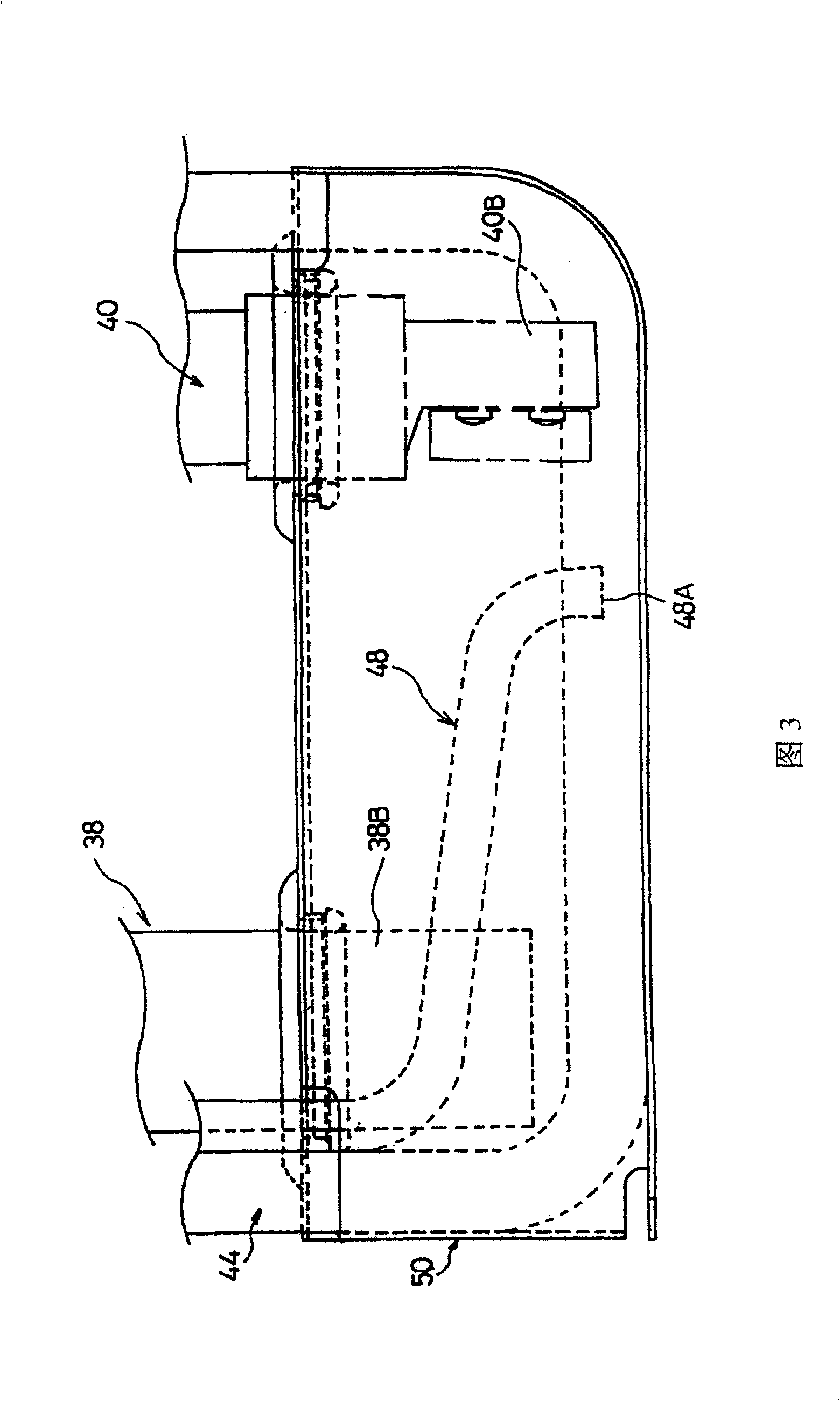
On the upper surface of a container body, there are installed at least a base section of a water level meter for detecting the remaining amount of a liquid reducing agent, a base section of a concentration meter for detecting the concentration of the liquid reducing agent, a heat exchanger surrounding each of detection sections of the water level meter and the concentration meter and exchanging heat between an engine coolant and the liquid reducing agent by circulating the engine coolant, and a suction tube provided between the water level gauge and the concentration meter and sucking the liquid reducing agent from the bottom of the container body. A substantially box-like protector is installed so as to surround the water level meter, concentration meter, and suction tube that are positioned at the lower part of the heat exchanger. Heat discharged from the lower part of the heat exchanger is confined inside the protector, and convection is produced in the confined region. By this, the liquid reducing agent frozen around the water level meter, concentration meter, and suction tube is efficiently thawed.

Description

technical field [0001] The present invention relates to the structure of a reductant container for storing a liquid reductant used in an exhaust gas purification device for reducing and purifying nitrogen oxides (NOx) in exhaust gas, and particularly relates to a structure that can be used in a short time after starting an engine. Technology that exerts exhaust gas purification functions. Background technique [0002] Japanese Unexamined Patent Publication No. 2000-27627 (Patent Document 1) discloses an exhaust gas purification system as a catalytic purification system for removing NOx contained in engine exhaust gas. [0003] The above-mentioned exhaust purification device injects and supplies a liquid reductant corresponding to the engine operating state upstream of the exhaust gas of the reduction catalyst arranged on the engine exhaust pipe, so that the NOx in the exhaust gas and the liquid reductant undergo a catalytic reduction reaction, and the NOx purification treat...

Claims


Application Information

Patent Timeline
Patent Type & Authority Patents(China)
IPC IPC(8): F01N3/08F01N3/24B01D53/94
Inventor 佐藤博一栗田弘之松永英树尾作靖司近藤俊男福田喜代史
Owner NISSAN DIESEL MOTOR CO
Learn More