Self focusing array ultrasonic energy changer

An ultrasonic transducer and self-focusing technology, applied in the field of biomedical engineering, can solve the problems of too small focal area and high intensity, and achieve the effects of excellent performance, common material selection, and flexible work.

Inactive Publication Date: 2008-12-31
SHANGHAI JIAOTONG UNIV
View PDF5 Cites 3 Cited by
  • Summary
  • Abstract
  • Description
  • Claims
  • Application Information

AI Technical Summary

Problems solved by technology

However, this technology has obvious shortcomings for the focused ultrasonic conformal heating system: its self-focusing ultrasonic transducer can only form a fixed-position, constant-sized focal region, and the focal region is too small and the intensity is too high

Method used


Image

  • Self focusing array ultrasonic energy changer
  • Self focusing array ultrasonic energy changer

Examples


Embodiment Construction

[0016] In order to better understand the technical solutions of the present invention, a further detailed description will be made below in conjunction with the accompanying drawings and embodiments.

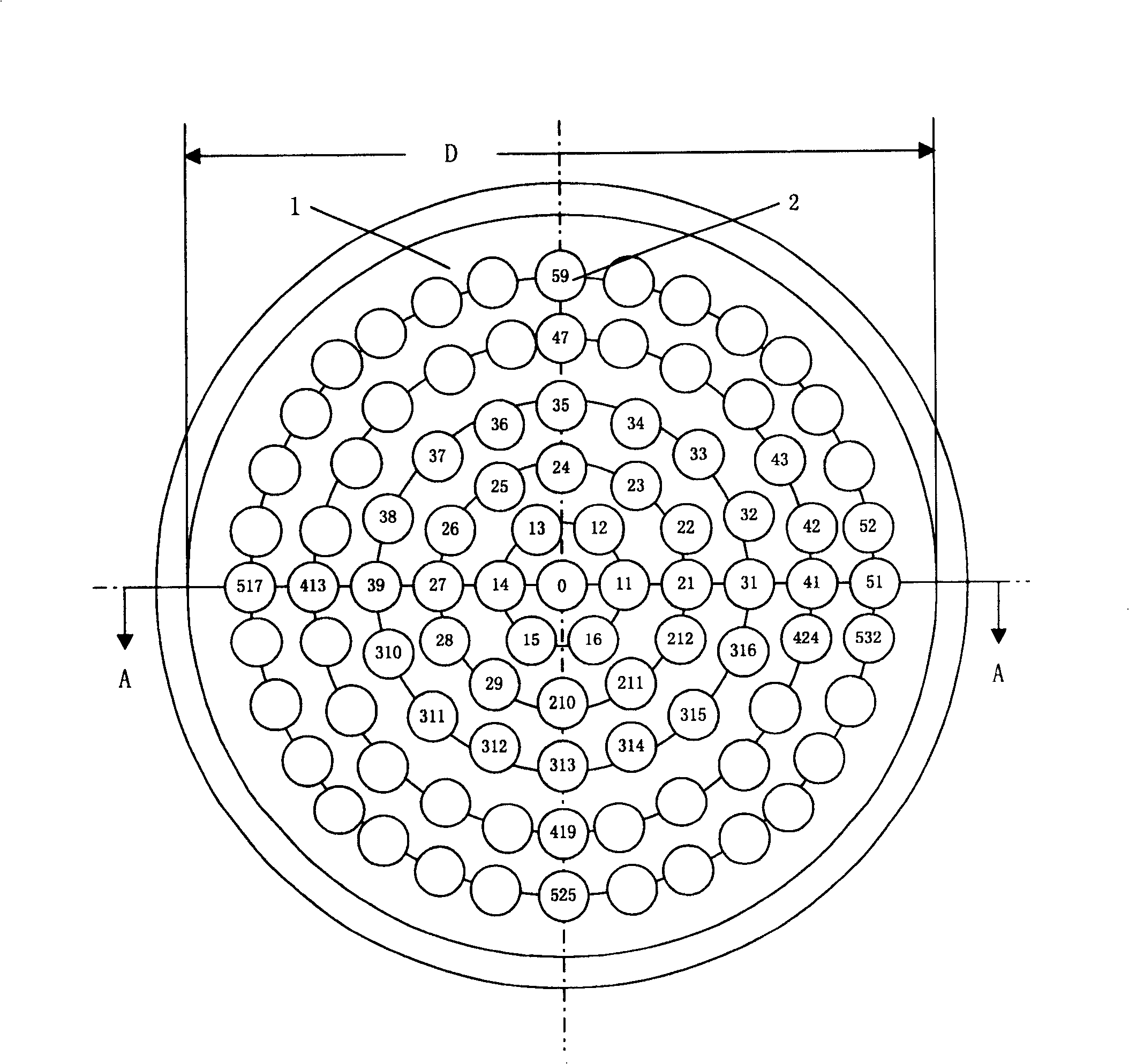
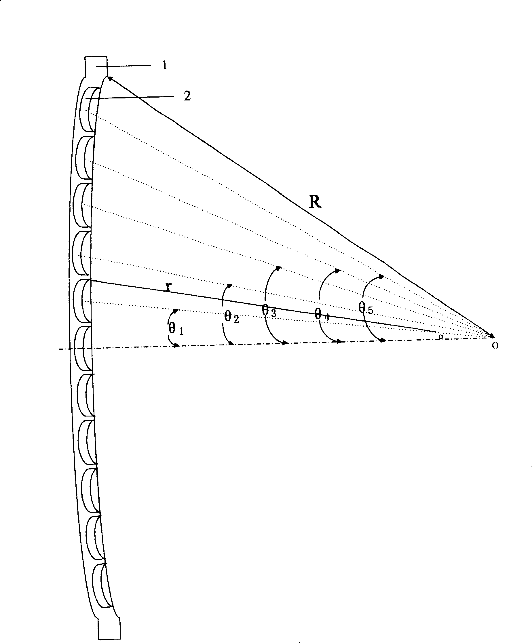
[0017] The structure of the self-focusing array ultrasonic transducer of the present invention is as follows: figure 1 , figure 2 As shown, it consists of a large-aperture rigid spherical crown body 1 and several spherical ultrasonic transducer array elements 2 discretely distributed in a concentric ring array structure. The central array element numbered 0 is centered on the center of the spherical crown, and the remaining array elements are discretely distributed on several layers of concentric rings with the center of the spherical crown as the origin, and the array elements on each layer of concentric rings are distributed at equiangular intervals. The number of array elements on each layer is different, and each array element has an independent electrical excitation signa...


PUM


Abstract

A self-focusing ultrasonic transducer array for the shape-adaptive ultrasonic heating system is composed of a large-diameter rigid spherical crown, several spherical ultrasonic transducer units arranged on the concentric rings in said spherical crown, and the signal exciting system with electric exciting lines for said transducer units, one for one.

Description

technical field [0001] The invention relates to an ultrasonic transducer, in particular to a self-focusing array ultrasonic transducer, which is applied to a focused ultrasonic conformal heating system and belongs to the technical field of biomedical engineering. Background technique [0002] The self-focusing ultrasonic transducer can not only penetrate the ultrasonic energy emitted outside the body into human tissue, but also concentrate the ultrasonic energy near its geometric focus to form a high-intensity area—the focal region. Due to the large amount of energy deposited in the focal area, the temperature of the tissue inside it rises rapidly, reaching a treatment temperature of 43°C, while the temperature of the tissues outside the focal area is only slightly increased due to a small amount of energy deposition. Combining this targeted heating technology with controlled-release drugs can ensure that the drug is only released in the designated area that needs to be trea...

Claims


Application Information

Patent Timeline
Patent Type & Authority Patents(China)
IPC IPC(8): A61N7/00A61N7/02
Inventor 陈亚珠萧祥麟倪养华
Owner SHANGHAI JIAOTONG UNIV
Why Eureka
Try Eureka