Sewing machine with dust collector

A vacuum device and sewing machine technology, which is applied in the field of sewing machines, can solve problems such as the trouble of blowing air into the hand-held spray gun, the deterioration of the working environment, and cumbersome cleaning operations, etc., so as to improve the self-cleaning performance, improve the self-cleaning performance, and prevent poor sewing Effect

Inactive Publication Date: 2009-01-07
YAMATO SEWING MASCH MFG CO LTD
View PDF6 Cites 0 Cited by
  • Summary
  • Abstract
  • Description
  • Claims
  • Application Information

AI Technical Summary

Problems solved by technology

When this kind of dust is scattered and collected inside the base of the cylindrical sewing machine, which contains sewing parts such as the looper, the cloth feeding mechanism, and the measuring mechanism, it will not only easily cause the needle thread and the looper return thread to not be formed according to the regulations, and the thread to be skipped, etc. Poor sewing, and the accumulated dust interferes with movable parts such as needles and loopers, which will cause deformation or damage of these movable parts.
[0003] As a method to prevent such bad sewing, the cleaning method generally used in the past is to interrupt the sewing machine during sewing, and blow air into the base of the cylindrical sewing machine with a hand-held spray gun, thereby scattering the accumulated dust to remove it. It is removed, but in this case, not only is it troublesome to blow air into the hand-held spray gun and cumbersome cleaning work is required, but also the sewing efficiency is reduced due to frequent interruption of the sewing operation
In addition, there is another problem that the dust that is blown by the air is immediately covered around the base of the cylinder sewing machine, deteriorating the working environment.
[0006] However, in the above-mentioned sewing machine with a self-cleaning device proposed in the past, in the case of having the former forced suction type self-cleaning device, even in the inside of the base portion of the cylindrical sewing machine, the pipe connected to the suction device or At the opening end of the suction port at one end of the pipe, the suction force is different between the part close to the opening end and the part far away from the opening end. Due to the relationship between the suction force difference and the distance to the opening end, the suction air flow in the base of the sewing machine Concentrate and flow along a specific trajectory, inevitably causing drift
Therefore, the dust generated in the deflected flow area of ​​the suction air can be completely sucked away, but the dust generated in parts other than the deflected flow area cannot be sucked away, but remains in the sewing machine base, and the remaining dust will accumulate in the sewing machine. Inside the base
In addition, the amount and form of dust accumulation in the base of the sewing machine are changing all the time, and the drift area will change according to the conditions such as the amount of accumulation and the form of accumulation. The most dusty position is close to the position directly below the needle plate. However, with the change of the bias flow area, the position of the strongest attraction force also changes. The feeding platform of the cloth feeding mechanism fully exerts its dust-absorbing performance
[0007] In the case of the latter air blowing type self-cleaning device, the air flow blown into the sewing machine base will be biased due to the position of the gap between the opening end position of the air blowing port and the sewing machine base, and many positions. Phenomenon, it is difficult to maintain uniform positive pressure in the entire area of ​​the sewing machine base
Therefore, it cannot be avoided that part of the dust enters the inside of the base portion of the sewing machine.
In addition, the air flow containing dust is often blown out from the sewing machine base to the outside and scattered to the surroundings, so there is a big problem that the working environment of sewing workers is extremely unsanitary

Method used


Image

  • Sewing machine with dust collector
  • Sewing machine with dust collector
  • Sewing machine with dust collector

Examples


Embodiment Construction

[0020] Embodiments of the present invention described in claims 1-4 are described below with reference to the accompanying drawings.

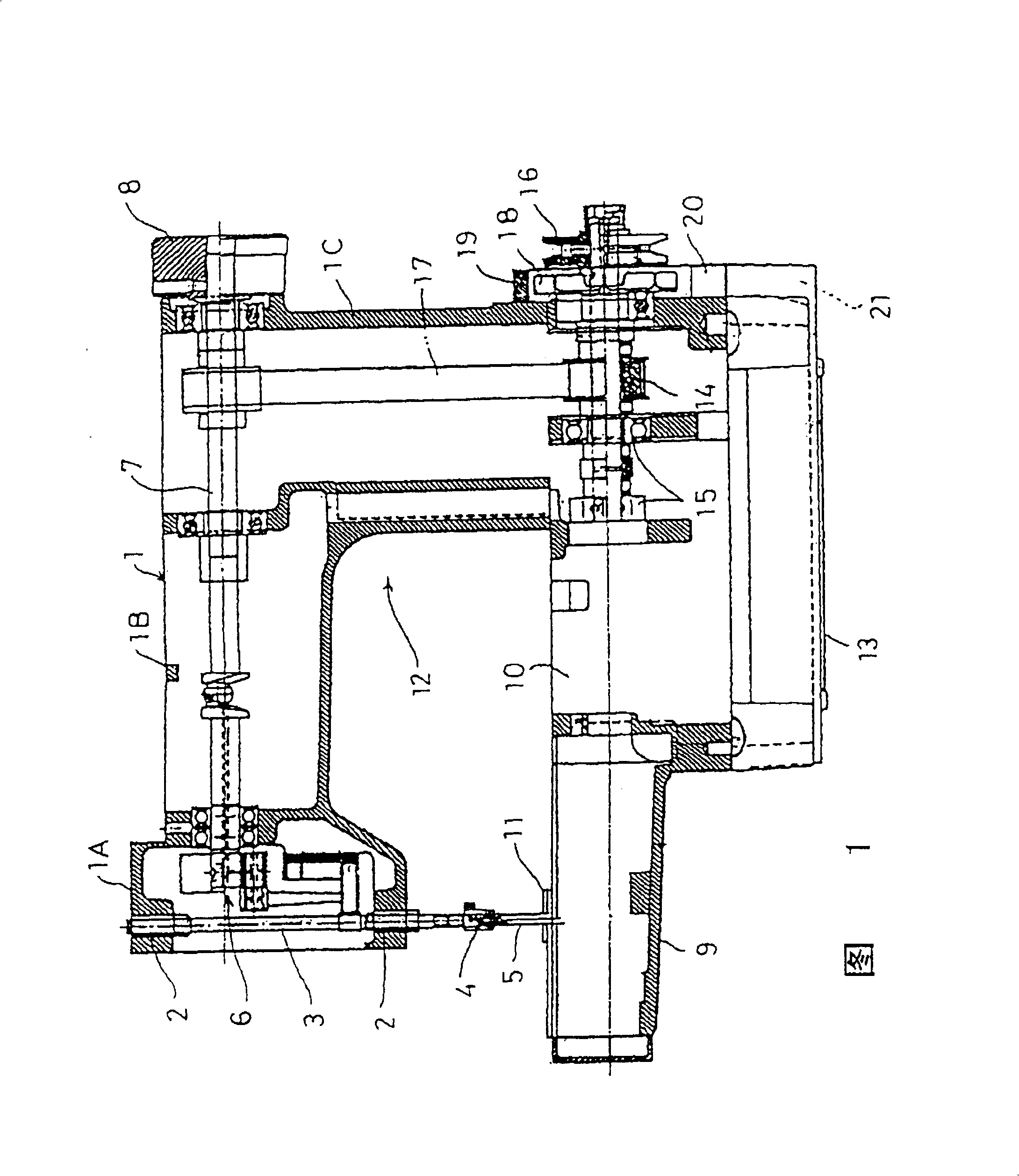
[0021] Fig. 1 is a partially cutaway front view of a cylindrical base type multi-needle flat sewing machine with a dust suction device according to the present invention. In this figure, 1 is the arm of the sewing machine, and the needle bar 3 is supported on the front end 1A of the needle bar 3 through the bearing 2 so that it can reciprocate in the up and down direction. department. In addition, the upper shaft 7 for driving is also supported through, and the upper shaft 7 for driving can make the needle bar 3 reciprocate up and down through the known needle bar driving mechanism 6 provided in the above-mentioned front end portion 1A. A handwheel 8 is fixed to the protruding end on the right side of the upper shaft 7 .

[0022] 9 is a cylindrical sewing machine base portion, which is integrally fixed to the sewing machine base base portion ...


PUM


Abstract

A suction pipe, which has a tip suction port capable of sucking the air stream including the dust generated below the throat plate and intermediate suction port capable of sucking the air stream including the dust generated near a looper thread handling area, is inserted into the tubular sewing machine bed section fitted with the throat plate at the upper face section and storing sewing components inside. A forced air guide section, which can guide air under the suction pipe in the tubular sewing machine bed section and forcibly move the guided air toward the suction ports of the suction pipe, is provided. The structure can minimize a dust accumulation quantity in a tubular sewing machine bed section by invariably efficiently sucking and removing the dust most generated below a throat plate without deteriorating the work environment.

Description

technical field [0001] The invention relates to a sewing machine with a dust suction device. Specifically, the sewing machine with dust suction device that the present invention relates to is that the needle plate is installed on the upper surface of the cylindrical sewing machine base protruding from the base of the sewing machine base, and the sewing parts such as the looper, the cloth feeding mechanism, the measuring mechanism, etc. The sewing machine housed inside can prevent poor sewing and damage to parts caused by the accumulation of dust such as thread ends and cloth wool generated during sewing such as flat seams, etc., in the base of the cylindrical sewing machine. The working environment deteriorates due to dust flying around the sewing place. Background technique [0002] When utilizing a sewing machine to sew, dust such as thread ends and cloth hairs are the most generated near the feeding platform of the cloth feeding mechanism located at the lower part of the...

Claims


Application Information

Patent Timeline
Patent Type & Authority Patents(China)
IPC IPC(8): D05B81/00D05B1/10D05B73/06
Inventor 水崎隆田中良幸
Owner YAMATO SEWING MASCH MFG CO LTD
Why Eureka
Try Eureka