Single current bias circuit of current source

A bias circuit, single current technology, applied in the direction of adjusting electrical variables, control/regulating systems, instruments, etc.

Inactive Publication Date: 2009-01-07
SHANGHAI BEILING
View PDF3 Cites 0 Cited by
  • Summary
  • Abstract
  • Description
  • Claims
  • Application Information

AI Technical Summary

Problems solved by technology

[0010] The disadvantage of this circuit is that it also uses two current bias circuits, and the circuit structure has two limiting conditions V gs4 equal to V gs2 , V ds5 equal to V dsat1

Method used


Image

  • Single current bias circuit of current source
  • Single current bias circuit of current source
  • Single current bias circuit of current source

Examples


Embodiment Construction

[0019] In order to have a deeper understanding of the bias circuit of the present invention, the present invention will be described in detail below in conjunction with the above-mentioned drawings.

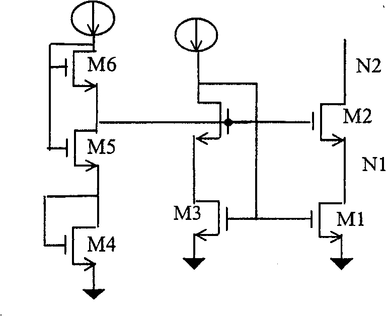
[0020] see Figure 4 As shown, the bias circuit of the present invention includes several MOS transistors M3, M4, M5, and M6 connected in series. In this embodiment, four MOS transistors are used. Among the two adjacent MOS transistors, the source of one MOS transistor is connected to the drain of the other MOS transistor. The drain of the uppermost MOS transistor M6 is connected to the constant current source, the gate of the uppermost MOS transistor M6 and its adjacent MOS transistor M5 are connected in parallel and then connected to the constant current source, and the source of the lowermost MOS transistor M3 connected to the common terminal, the gate of the MOS transistor M3 is connected to the drain of the adjacent MOS transistor M4, and the gate of the MOS transistor M4 a...


PUM


Abstract

This invention discloses a single current bias circuit of current source, which comprises several serial MOS tubes with one source electrode connected to the leakage electrode of the other one. The top MOS tube leakage electrode is connected with the constant current source. The upper MOS tube and its adjacent MOS tube grating are paralleled and connected into the constant source. The bottom MOS tube source electrode is connected with the common end.

Description

technical field [0001] The invention relates to a Cascode analog current source based on MOS elements, more specifically a single current bias circuit of a current source. Background technique [0002] In analog electronic circuits, current sources are widely used as the transmission medium of analog current and voltage signals. The indicators to measure the performance of the current source include the output impedance of the current source, the dynamic range of the output node voltage, and the current tracking characteristics. Because the Cascode current source can provide very high output impedance and good current tracking characteristics, it has been widely used, but the voltage dynamic range of its output node is limited by the bias voltage of the Cascode current source structure, so it needs to be biased correctly. Set the Cascode current source to increase its output node voltage dynamic range. [0003] figure 1 A bias circuit of the simplest Cascode current sourc...

Claims


Application Information

Patent Timeline
Patent Type & Authority Patents(China)
IPC IPC(8): G05F1/46
Inventor 刘家洲
Owner SHANGHAI BEILING
Why Eureka
Try Eureka