Optical fiber connector end face parameter measuring device and measuring method

A fiber optic connector and parameter measurement technology, which is applied in the optical field, can solve the problems of low test accuracy, small dynamic range, and low measurement efficiency, and achieve the effect of good repeatability, high confidence, and clear observation

Active Publication Date: 2020-02-28
XI'AN INST OF OPTICS & FINE MECHANICS - CHINESE ACAD OF SCI
View PDF6 Cites 0 Cited by
  • Summary
  • Abstract
  • Description
  • Claims
  • Application Information

AI Technical Summary

Problems solved by technology

[0005] In order to solve the technical problems of the existing optical fiber connector end-face parameter measurement method in the background technology that is easily affected by the environment, the test accuracy is not high, the measurement efficiency is low, and the dynamic range is small, the present invention proposes a fiber optic connector end-face parameter measurement device and measurement method. method,

Method used


Image

  • Optical fiber connector end face parameter measuring device and measuring method
  • Optical fiber connector end face parameter measuring device and measuring method
  • Optical fiber connector end face parameter measuring device and measuring method

Examples


Embodiment Construction

[0040] The present invention will be further described below in conjunction with the accompanying drawings.

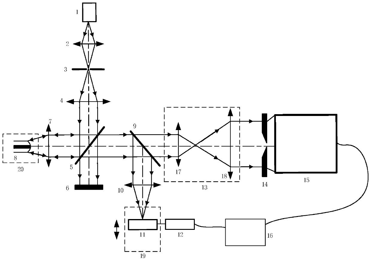
[0041] Such as figure 1 As shown, the optical fiber connector end face parameter measuring device provided by the present invention includes a light source 1, a converging mirror 2, a target plate 3, a collimating mirror 4, a beam splitter 5 and an absorber 6 arranged sequentially along the same optical path; Define the surface of the No. 1 beam splitter 5 facing the collimating mirror 4 as the first mirror surface, and on the reflected light path after the outgoing light beam of the collimating mirror 4 is reflected by the first mirror surface, a No. 1 microscopic objective lens 7 is arranged; The beam splitter 9, the beam expander system 13, the positioning reference structure 14 and the Shaker-Hartmann wavefront sensor 15 are sequentially arranged on the transmission optical path after the outgoing beam of the objective lens 7 is transmitted through the first mirror...


PUM


Abstract

In order to solve the technical problems that the existing optical fiber connector end face parameter measurement method is susceptible to the environmental influence, the test accuracy is, the measurement efficiency is low and the dynamic range is small, the invention provides an optical fiber connector end face parameter measurement device and measurement method. The measurement device comprises a light source, a convergent mirror, a target plate, a collimating mirror, a first beam splitter and an absorber, which are arranged in sequence along the same light path; one surface of the first beam splitter facing to the collimating mirror is defined as a first mirror surface, and a first microobjective is arranged on a reflection light path of an outgoing beam of the collimating mirror after being reflected by the first mirror surface; a second beam splitter, a beam expansion system and a Shaker-Hartmann wavefront sensor are arranged on a transmission light path of the outgoing beam ofthe first microobjective after being transmitted by the first mirror surface in sequence; a second microobjective and an imaging detector are arranged on the reflection light path of the second beam splitter in sequence; and the imaging detector arranged on a one-dimensional electronic control translation platform, and the one-dimensional electronic control translation platform is connected with acontrol and data analysis computer via a driver.

Description

technical field [0001] The invention belongs to the field of optics, and relates to a measuring device and a measuring method for an end face parameter of an optical fiber connector. The parameters of the end face of the optical fiber connector include the three-dimensional shape of the end face of the optical fiber connector, the radius of curvature, the grinding eccentricity and the height of the optical fiber. Background technique [0002] The function of the fiber optic connector is to connect the fibers so that the optical signal can be transmitted in the fiber optic system with the lowest loss. It is an important component of the fiber optic communication system. In order to minimize the impact of optical fiber connectors on the system when intervening in optical communication lines, its optical performance must be guaranteed, and the factor to measure the optical performance of optical fiber connectors is not external reasons, but the quality of its own end face. The...

Claims


Application Information

Patent Timeline
Patent Type & Authority Patents(China)
IPC IPC(8): G01B11/24G01B11/255G01B11/06
CPCG01B11/0608G01B11/24G01B11/255
Inventor 段亚轩达争尚李红光陈永权袁索超王璞李铭寇经纬王拯洲
Owner XI'AN INST OF OPTICS & FINE MECHANICS - CHINESE ACAD OF SCI
Why Eureka
Try Eureka