Jet printing valve based on carbon nano-tube tiny bubble generator and method of producing the same
A micro-bubble generator and carbon nanotube technology, applied in printing and other directions, can solve problems such as high power consumption, achieve the effects of low power consumption, small size, and overcome high power consumption
- Summary
- Abstract
- Description
- Claims
- Application Information
AI Technical Summary
Problems solved by technology
Method used
Image
Examples
Embodiment 1
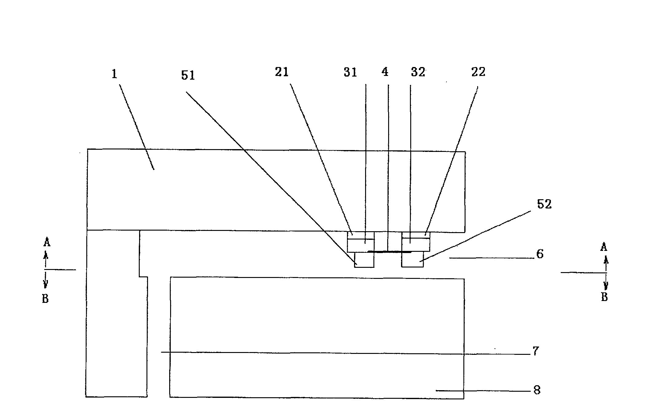
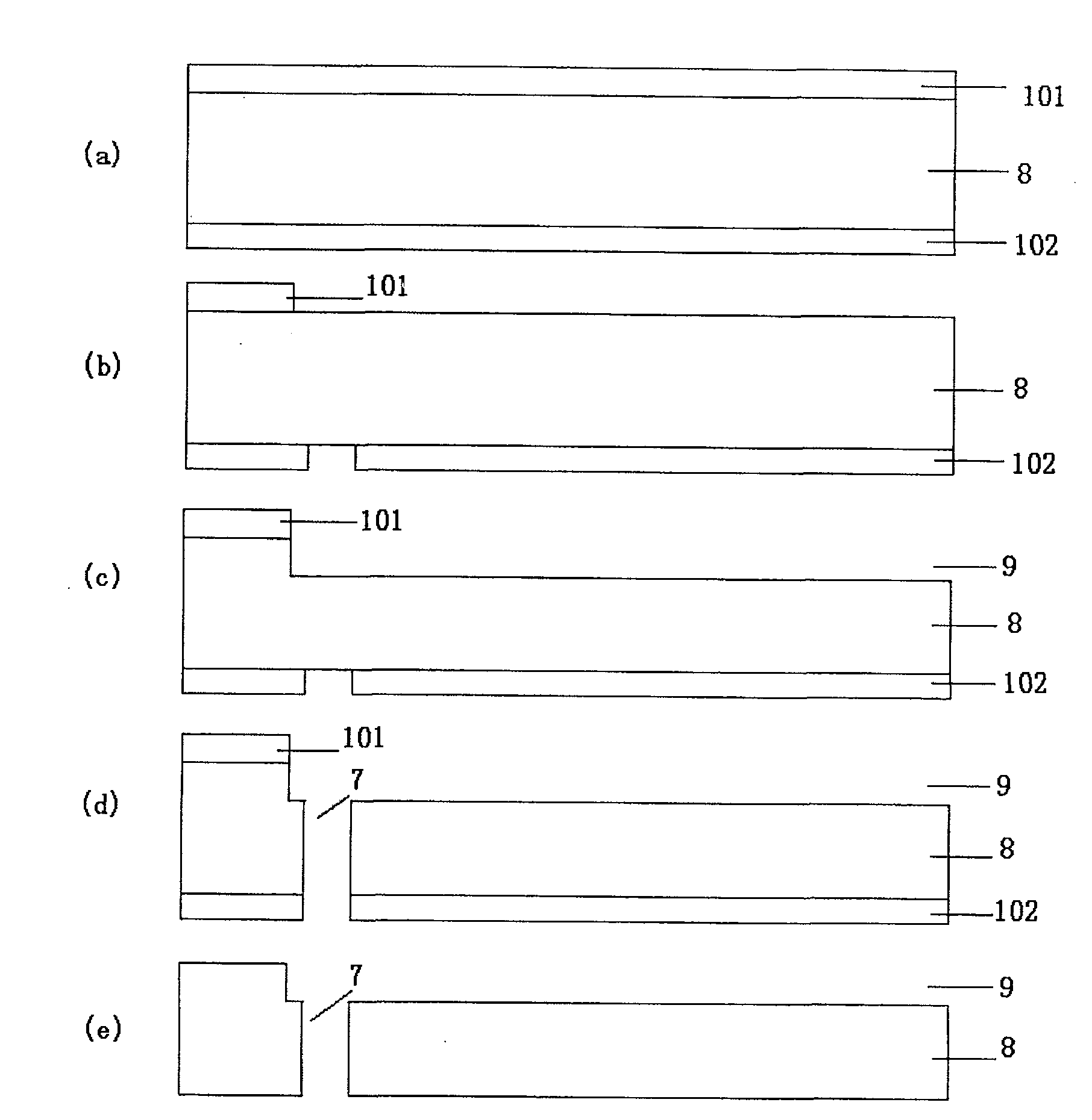
[0046] (1) Surface treatment and cleaning of the glass substrate 1 according to a standard CMOS process;
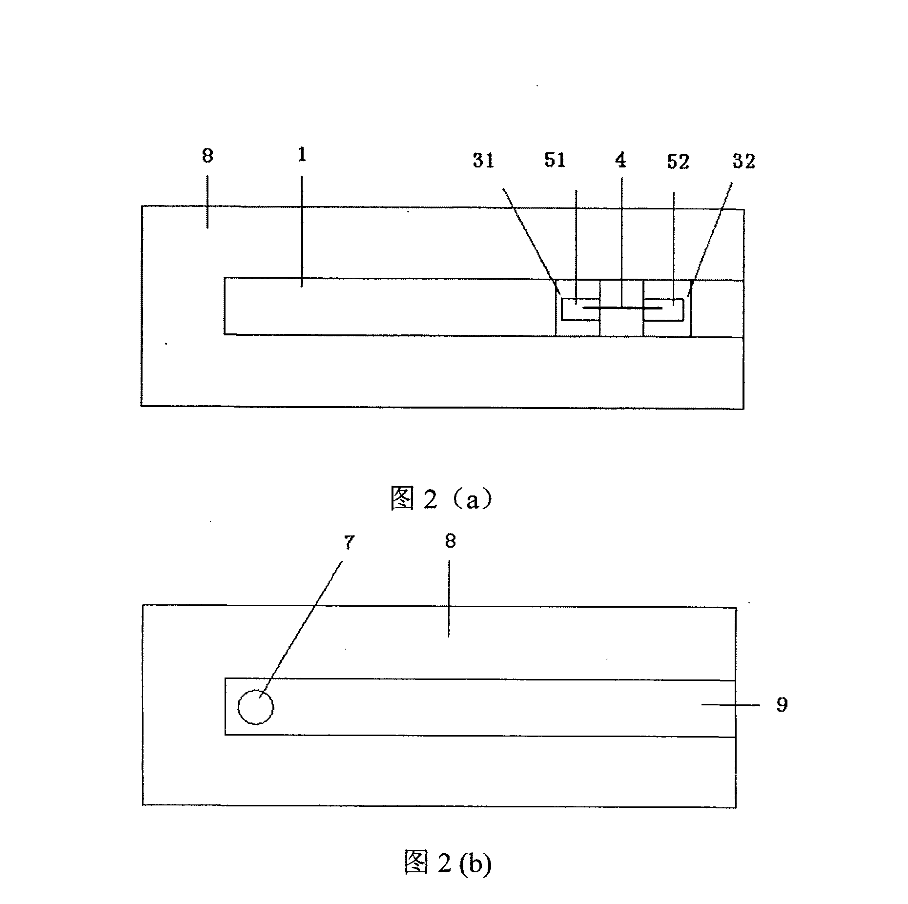
[0047] (2) The carbon nanotube microbubble generator is prepared on the glass substrate 1, and the process is as follows:
[0048] (2.1) Evaporating titanium with an electron beam to form a titanium film with a thickness of 20nm;
[0049] (2.2) Evaporating gold by electron beam to form a gold film with a thickness of 400nm;
[0050] (2.3) Form gold electrodes 31, 32 using the existing lift-off process (lift-off), and the distance between the gold electrodes 31, 32 is 5 μm;
[0051] (2.4) Mix carbon nanotubes 4 with a diameter of 10 to 30 nm and absolute ethanol solvent in a ratio of 0.01 mg / ml, and disperse the carbon nanotubes uniformly through ultrasound;
[0052] (2.5) 1MHz, 8V AC voltage is loaded between the gold electrodes 31 and 32 on the glass substrate 1, and the carbon nanotube suspension is dropped between the electrodes with a micro-syringe. When the solvent e...
Embodiment 2
[0064] (1) Surface treatment and cleaning of the glass substrate 1 according to a standard CMOS process;
[0065] (2) The carbon nanotube microbubble generator is prepared on the glass substrate 1, and the process is as follows:
[0066] (2.1) Adopt sputtering titanium to form a titanium film with a thickness of 30nm;
[0067] (2.2) Adopt sputtering gold to form a gold film with a thickness of 300nm;
[0068] (2.3) Form gold electrodes 31, 32 using the existing lift-off process (lift-off), and the distance between the gold electrodes 31, 32 is 1 μm;
[0069] (2.4) Mix carbon nanotubes 4 with a diameter of 10 to 30 nm and absolute ethanol solvent in a ratio of 0.005 mg / ml, and disperse the carbon nanotubes uniformly by ultrasonication;
[0070] (2.5) 0.5MHz, 5V AC voltage is loaded between the gold electrodes 31 and 32 on the glass substrate 1, and the carbon nanotube suspension is dropped between the electrodes with a micro-injector. When the solvent evaporates completely, t...
Embodiment 3
[0082] (1) surface-treating and cleaning the silicon substrate 1 with the oxide layer grown therein according to the standard CMOS process;
[0083] (2) The carbon nanotube microbubble generator is prepared on the glass substrate 1, and the process is as follows:
[0084] (2.1) Adopt sputtering titanium to form a titanium film with a thickness of 30nm;
[0085] (2.2) Adopt sputtering gold to form a gold film with a thickness of 300nm;
[0086] (2.3) Form gold electrodes 31, 32 using the existing lift-off process (lift-off), and the distance between the gold electrodes 31, 32 is 10 μm;
[0087] (2.4) Mix carbon nanotubes 4 with a diameter of 10 to 30 nm and absolute ethanol solvent in a ratio of 0.05 mg / ml, and disperse the carbon nanotubes uniformly through ultrasound;
[0088] (2.5) 0.8MHz, 10V AC voltage is loaded between the gold electrodes 31 and 32 on the glass substrate 1, and the carbon nanotube suspension is dropped between the electrodes with a micro-injector. When ...
PUM
| Property | Measurement | Unit |
|---|---|---|
| thickness | aaaaa | aaaaa |
| thickness | aaaaa | aaaaa |
| diameter | aaaaa | aaaaa |
Abstract
Description
Claims
Application Information
 - R&D
- Intellectual Property
- Life Sciences
- Materials
- Tech Scout
- Unparalleled Data Quality
- Higher Quality Content
- 60% Fewer Hallucinations
Browse by: Latest US Patents, China's latest patents, Technical Efficacy Thesaurus, Application Domain, Technology Topic, Popular Technical Reports.
© 2025 PatSnap. All rights reserved.Legal|Privacy policy|Modern Slavery Act Transparency Statement|Sitemap|About US| Contact US: help@patsnap.com


