Motor centrally axle coupling structure

A center shaft and pivot joint technology, applied in the field of motor center shaft pivot joint structure, can solve problems such as loosening and falling, motor rotation noise, rotor deflection, etc., to achieve the effect of avoiding loosening and falling, and improving stability

Active Publication Date: 2009-01-07
SUNONWEALTH ELECTRIC MACHINE IND
View PDF5 Cites 3 Cited by
  • Summary
  • Abstract
  • Description
  • Claims
  • Application Information

AI Technical Summary

Problems solved by technology

[0006] In view of the above problems, the main purpose of the present invention is to provide a pivot joint structure of the central shaft of the motor, which can simultaneously solve the problems of motor rotation noise, rotor deflection, and even loosening and falling, and relatively improve the stability of motor operation

Method used


Image

  • Motor centrally axle coupling structure
  • Motor centrally axle coupling structure
  • Motor centrally axle coupling structure

Examples


Embodiment Construction

[0026] In order to describe the structure and characteristics of the present invention in detail, several preferred embodiments are listed below and the relative positions of the various components of the present invention are illustrated with reference to the accompanying drawings.

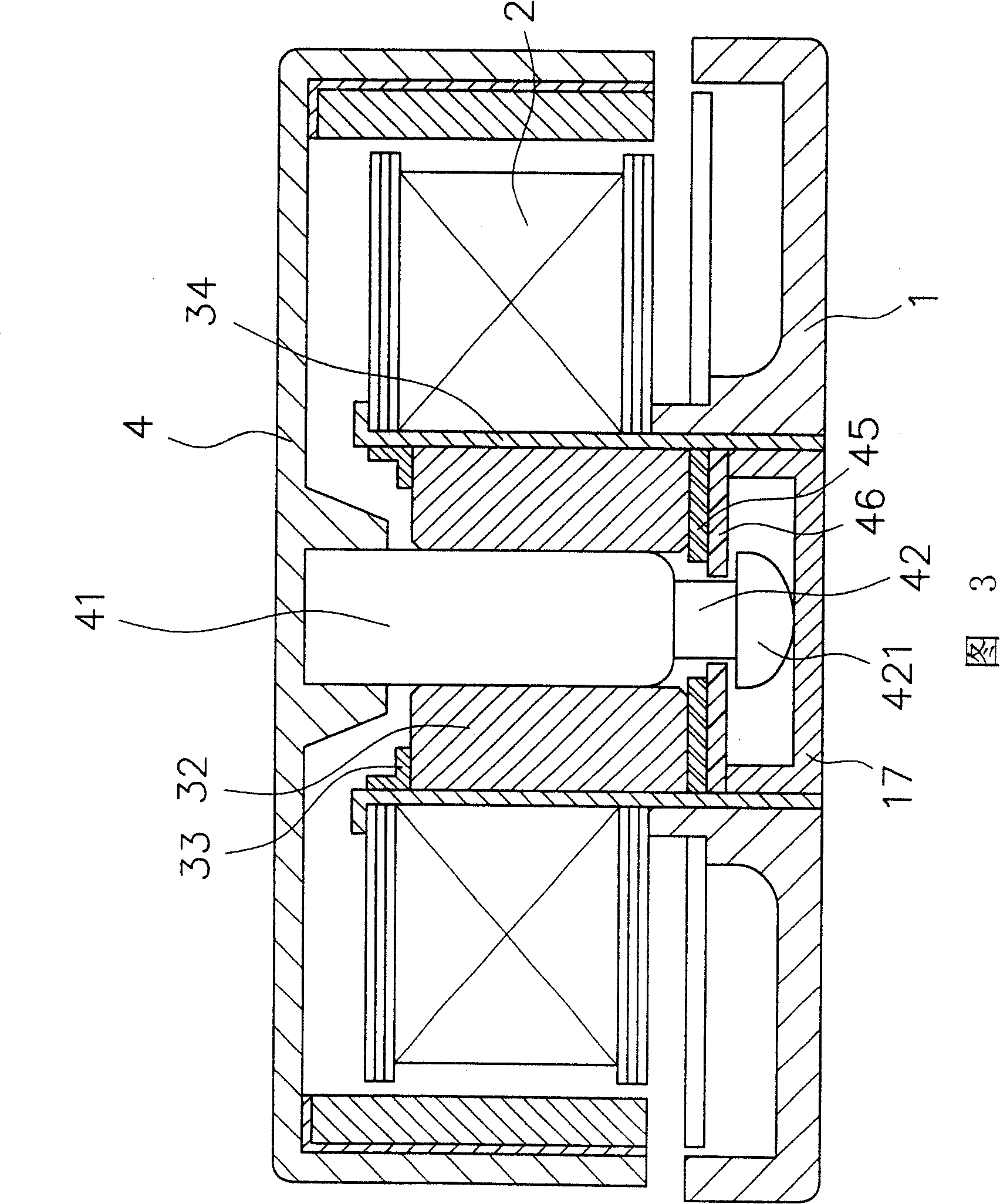
[0027] As shown in Figure 3, the motor is equipped with a shaft tube 34 on a shell base 1. The shaft tube 34 can be integrally formed by the shell base 1, or can be combined and fixed on the shell base 1, and the outer circumference of the shaft tube 34 is sleeved with the stator base. 2. There is a bearing 32 inside, the central shaft 41 of the rotor 4 can be rotated in the center of the bearing 32, and one end of the central shaft 41 is the top 421, and the end side near the top 421 has a ring groove 42 with a smaller outer diameter .

[0028] The bearing 32 is fixed at a predetermined position by the positioning ring 33 above it and the center cover 17 below it, and at least two snap rings are...


PUM


Abstract

The invention relates to a central axle connecting structure of motor, which comprises: an axial tube on a frame, a bearing inside the axial tube, a central axle through with bearing and rotating whose end near the contact part has smaller annular groove, at least two clamping rings as first and second clamping rings clamped at the annular groove of center axle while the rigidity of first clamping ring is larger than second one; therefore, the invention can reduce rotation noise and vibration of rotor, to improve the operation stability.

Description

technical field [0001] The invention relates to a pivot joint structure of a central shaft of a motor, which is used for buckling and positioning the central shaft so that the motor rotor can rotate corresponding to the stator seat without falling off. Background technique [0002] Such as figure 1 As shown, it is a schematic cross-sectional view of the patent case "Pivoting Structure of Small Motor Rotor" with Taiwan Application No. 88219447, which is equipped with a metal shaft tube 3 on a shell base 1, and the outer circumference of the metal shaft tube 3 is sleeved with a stator seat 2. A bearing 32 is installed inside, the central shaft 41 of the rotor 4 can be threaded and rotated in the center of the bearing 32, and the function of the buckle 43 is to fasten and position the central shaft 41 so that the rotor 4 can correspond to the stator seat 2 Spin without falling off. [0003] The buckle 43 is a buckle made of metal. Because the buckle made of metal itself has b...

Claims


Application Information

Patent Timeline
Patent Type & Authority Patents(China)
IPC IPC(8): H02K7/08H02K5/16
Inventor 洪银树洪庆升
Owner SUNONWEALTH ELECTRIC MACHINE IND
Why Eureka
Try Eureka