
Machining clamp for numerical control machine tool

A technology of CNC machine tools and fixtures, which is applied in the direction of manufacturing tools, metal processing equipment, metal processing machinery parts, etc., can solve the problems of inconvenient loading and unloading of parts, loosening and falling of workpieces, etc., so as to improve the fixing effect and prevent loosening The effect of taking it off and fixing it firmly

Inactive Publication Date: 2016-12-07
刘书雄
View PDF7 Cites 2 Cited by
  • Summary
  • Abstract
  • Description
  • Claims
  • Application Information

AI Technical Summary

Problems solved by technology

Although the positioning and clamping of the inner hole can ensure the clamping effect, it is inconvenient to clamp and unload the workpiece, and the workpiece is easy to loosen and fall from the fixture

Method used


Image

  • Machining clamp for numerical control machine tool
  • Machining clamp for numerical control machine tool

Examples


Embodiment Construction

[0011] The following will clearly and completely describe the technical solutions in the embodiments of the present invention with reference to the accompanying drawings in the embodiments of the present invention. Obviously, the described embodiments are only some, not all, embodiments of the present invention. Based on the embodiments of the present invention, all other embodiments obtained by persons of ordinary skill in the art without making creative efforts belong to the protection scope of the present invention.

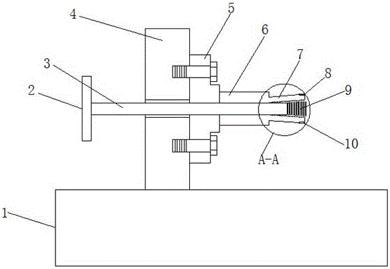
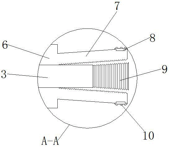
[0012] see Figure 1-2 , the present invention provides a technical solution: a machining fixture for a numerically controlled machine tool, comprising a numerically controlled workbench 1, on which a fixture mounting frame 4 is arranged, and the right side of the fixture mounting frame 4 is fixed with a fixture through bolts Seat 5, clamping column 6 is installed in the middle part of the right side of clamp fixing seat 5, and the right end of clamping column...


PUM


Abstract

The invention discloses a machining clamp for a numerical control machine tool. The machining clamp comprises a numerical control worktable. A clamp installation frame is arranged on the numerical control worktable. The right side face of the clamp installation frame is provided with a clamp fixing seat through bolts. A clamping column is installed at the middle portion of the right side face of the clamp fixing seat. Spring pieces are distributed at the right end of the clamping column at equal intervals in a surrounding manner. A horizontally-arranged adjusting rod is connected to the middle portion of the clamp installation frame in an inserted manner. A rotary handle is installed at the left end of the adjusting rod. The right end of the adjusting rod sequentially penetrates the clamp installation frame, the clamp fixing seat and the clamping column and extends to the outer portion of the right end of the clamping column. According to the machining clamp for the numerical control machine tool, the interior of a workpiece is fixed under the cooperation of the adjusting rod, the spring pieces and an adjusting screw, and therefore the workpiece and the clamping column can be firmly fixed, the workpiece is prevented from loosening and falling, the friction force between the spring pieces and the inner side face of the workpiece can be enlarged through friction protruding points on the surfaces of rubber pieces, and the fixing effect is improved.

Description

technical field [0001] The invention relates to the technical field of numerical control equipment, in particular to a processing fixture of a numerical control machine tool. Background technique [0002] When processing the outer surface of some workpieces with tapered holes, in order to ensure the processing quality, it is often necessary to ensure the coaxiality of the clamping. If a traditional three-jaw or four-jaw chuck is used for clamping, it is not only inconvenient to clamp, but also very time-consuming and laborious to measure the coaxiality after clamping. Therefore, when processing such workpieces, the inner hole can be positioned and clamped, and the coaxiality can be well guaranteed. Although positioning and clamping the inner hole can ensure the clamping effect, it is inconvenient to clamp and unload the workpiece, and the workpiece is easy to loosen and fall from the fixture. Contents of the invention [0003] The object of the present invention is to pr...

Claims


Application Information

Patent Timeline
Patent Type & Authority Applications(China)
IPC IPC(8): B23Q3/14
CPCB23Q3/14
Inventor 刘书雄
Owner 刘书雄
Learn More